29 65-0086—2
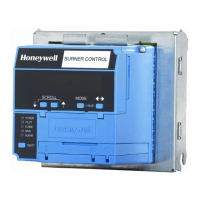
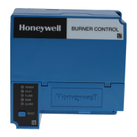
RM7895A,B,C,D
TROUBLESHOOTING
Total Hours, Fault History, Diagnostic Information and
Expanded Annunciator Terminal Status (if used). With
this information most problems can be diagnosed without
extensive trial and error testing. Information available in
the Diagnostic Information file includes: Device Type,
Device Suffix, Software Revision, Manufacturing Code,
Flame Amplifier Type, Flame Failure Response Time,
Selectable Jumper Configuration Status, Run/Test Switch
Status (RM7895C,D) and Terminal Status.
Diagnostic Information Index
The RM7895 with the optional Keyboard Display
Module can monitor input/output terminals and can
display the status of the terminal at the VFD (example;
Pilot Valve T8 ON<), see S7800A1001 Keyboard Dis-
play Module Specifications. A complete terminal de-
scription and number are provided. The display will
show the actual status of the terminal. If voltage is
detected at the terminal, ON is displayed; but if no
voltage is detected at the terminal, OFF is displayed.
Historical Information Index
The RM7895 has nonvolatile memory that allows the
Relay Module to retain Historical Information for the six
most recent lockouts. Each of the six lockout files retains
the cycle when the fault occurred, the hour of operation
when the fault occurred, and the fault message and burner
status when the fault occurred. The Historical Informa-
tion can be viewed by the optional S7800A1001 Keyboard
Display Module Specifications.
SERVICE NOTE: A Lockout condition or restart of a
RM7895 can be accomplished by pressing the reset
push-button on the RM7895, or by pressing a remote
reset pushbutton wired through an optional Keyboard
Display Module, DATA CONTROLBUS MOD-
ULE™, Extension Cable Assembly or Remote Reset
Module. A power-up reset will cause an electrical reset
of the RM7895 but will not reset a lockout condition.
SERVICE NOTE: Remove the access slot covers on the
sides of the Q7800A,B to check voltages.
CAUTION
Reinstall access slot covers on the Q7800A,B
Subbase after performing voltage checks.
SERVICE NOTE: Maximum ambient operating tem-
perature of a C7012E,F Series 1 through 6 will be
reduced to 125° F because of the duty cycle operation
of the RM7895 Relay Module.
!
TABLE 6—SEQUENCE AND STATUS HOLD INFORMATION.
NOTE: Normal sequences are in bold type, while abnormal sequences are not in bold type.
Sequence Status
INITIATE The LED indicates the burner status, POWER, which is a stabiliza-
tion period for the RM7895 to check for any fluctuations in AC line
voltage inputs or control input on power-up or during normal
operation. The timing of the INITIATE period is ten seconds before
entering STANDBY.
If the RM7895 is in a HOLD status, the following conditions could exist:
INITIATE HOLD: (AC Frequency/Noise) The LED indicates the burner status, POWER, and that it is waiting
for excess line noise to clear up. The burner sequence will not
advance into STANDBY until the excess line noise, which prevents
sufficient reading of the line voltage inputs, ceases or a line frequency
error is corrected (perhaps caused by using a 60 Hz device on a 50 Hz
line, or vice versa).
INITIATE HOLD: (AC Line Dropout) The LED indicates the burner status, POWER, and that AC Line
power has momentarily dropped out. The burner sequence will not
advance into STANDBY until the AC line voltage has stabilized
throughout the INITIATE sequence.
INITIATE HOLD: (AC Frequency) The LED indicates the burner status, POWER, and that line fre-
quency is faster than the expected value. The burner sequence will not
advance into STANDBY until the line frequency returns to the proper
value (perhaps caused by using a 60 Hz device on a 50 Hz line).
INITIATE HOLD: (Low Line Voltage) The LED indicates the burner status, POWER, and that low line voltage
has occurred. The burner sequence will not advance into STANDBY
until the line voltage is at a sufficient level for proper
operating parameters.
(continued)
 Loading...