.—
Fig. l-Mount
eaii
switch in one of positions
shown for
eibow turning vanes or sweep radius
is recommended.
UPSTREAM
-
MINIMUM
RETURN AIR
ALTERNATE
LOCATION. MOUNT SAIL
15
in.
[381 mm] MINIMUM
SWITCH ON THIS SIDE
OF DUCT, OPPOSITE
AIR ENTRANCE.
>
DO NOT MOUNT ON
TH!S
SIDE OF DUCT.
1“1
Y
I
-RETURN
AIR DUCT
I
DOWNSTREAM
I
MWU9
Fig. 2-hIlount eaii switch on center iine of duct
in one of angle-t positions shown for junction
duct work.
UPSTREAM
/ BEST LOCATION \
UPSTREAM
RETURN AIR DUCT
--1-1
OCIWN-
STREAM
M3007
Fig. 3-Mount
saii
switch in one of positions
shown for angle-t junction duct work. Transi-
tion in trunk is recommended.
&&
3MF
ik [381 mm] MINIMUM
i+
RETURN
OUCT OPPOSITE AIR
Y
Iv
ENTRANCES AS SHOWN.
DOWNSTREAM
I
AIR DUCT
M3110B
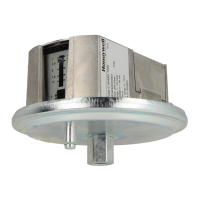
S688A
INSTALLATION
must beat
least 12 in. [305 mm] deep
and
8 in. [203 mm] wide
to allow operation of the sail without affecting the smooth
flow of
akin the duct. Airflow at the location may
beverticai
(up or down) or horizontal.
NOTE: When S688 is mounted in warm air, the sail life may
be reduced.
Refer to Figs. 1-3 for the best duct mounting location.
Mount the switch at least 6 in. [152 mm] upstream from an
elbow or junction, and at least 15 in. [381 mm] downstream
from an
ellmw
or junction. The switch must be located on the
opposite side of the duct from the air entrance.
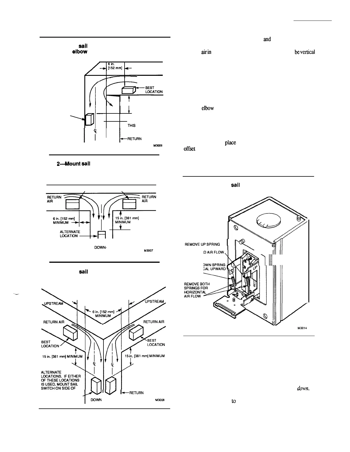
ADAPT SWITCH TO AIR FLOW DIRECTION
The S688A Saii Switch is provided with two counterbal-
ancing springs in
place
as shown in Fig. 4. These springs
off=t the effect of gravity for air flow direction.
IMPORTANT:
Never
use the sail switch with both springs
attached.
Fig. 4-Adapting
saii
switch to air flow direc-
tion.
Q
FOR VERTICAL
ill.\,
FKMOVEUPSPFIING
I
~
Y
00WNWARO AIR FLOW
\
1111
II
REMOVE DOWN SPRING
(
FOR VERTICAL UPWARO
AIR FLOW
6
i!zrl
1111
II
M?014
Adapt the sail switch to mounting position. (F52 requires
special instructions; see separate instructions.)
Standard Application
Horizontal air flow-remove both springs.
Vertical
upward air
flow-leave in place the spring that
is attached to the bracket marked up.
Remove the
spring that is attached to the bracket marked
abwn.
Vertical
downward air
flow-leave in place the spring
that is attached
to
the bracket marked
down. Remove
the
spring that is attached to the bracket marked
up.
3
60-2103-3

 Loading...