S688A
SPECIFICATIONS ● INSTALLATION ● ORDERING INFORMATION
Specifications
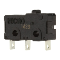
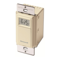
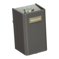
MODEL S688A Sail Switch.
ELECTRICAL RATINGS (Amperes):
,,
N.0.
Contacts
N.C.
Contacts
24 120 240
24 120 240
Vac
Vac
Vac
Vac Vac Vac
Full
2.0
2.0
1.0 1.0
1.0 0.5
Load
Lwked
12.0 12.0 6.0 6.0 6.0 3.0
Rotor
Resistive
5+0
5+0
2,5
2.5 2.5 2.5
SWITCHJNG
ACTION Spdt
snapacting
switch.
SAIL DATA:
Insertion length-10 in. [254 mm].
Maximum width-5 in. [127 mm].
Approximate area-26.2 in.
2
[1690
mmz].
Materk+mlyester
film sealed on music wire frame.
mu
AIRFLOW
N.O.
Contacts:
Makes-250
@m.
Breaks-75 fpm.
N.C.
Contacw
Makes-75 fpm.
Breaks-250 fpm.
MAXIMUM AMBIENT TEMPERATURES:
125° F [52° C] at switches.
170° F [77° C] at sail.
CASE DIMENSIONS: 2-5/16 in. [59 mm] high, 3-3/4 in.
[95 mm]
wide, 2-1/8 in. [54 mm] deep.
DUCT MOUNTING HOLE DIMENSIONS: 1-1/2 in.
[38 mm] by 2-1/4 in. [57 mm].
MOUNTING MEANS: Switch mounts on return air duct
with two sheet metal screws. An adhesive backed mount-
ing template is provided. Sail is inserted into duct through
1-1/2 in. [38 mm] by 2-1/4 in. [57 mm] hole.
MOUNTJNG POSITION: Mounts in vertical (up or down)
or horizontal airflow.
WIRJNG
KNOCKOUTS:
1/2
in. conduit knockout in either
end of ease.
FINISH: Zinc plated case and cover.
REPLACEMENT PARTS: Part no. 123773A Replacement
sail.
UNDERWRITERS’ LABORATORIES, INCL LISTED:
File No. E4436, Guide No. XAPX. For use in ambient
temperatures normally prevailing in
oecupiable
spaces,
which usually are not higher than 77°
F
[25° C] but
occasionally may be as high as 104° F [40° C] for brief
periods.
Installation
WHEN INSTALLING THIS PRODUCT...
1. Read these instructions carefully. Failure to follow
them could damage the product or cause a hazardous condi-
tion.
2. Check the ratings given in the instructions and on the
product
to
make sure the product is suitable for your applica-
tion.
3. Installer must
beatrained,experienced
service
techni-
cian.
4. After installation is complete, check out product op
eration as provided in these instructions.
/h
CAUTION
t
\
Disconnect power supply before beginning
install-
ation to prevent electrical shock or equipment
damage.
LOCATION
Locate the sail switch in the return air duct where the sail
will be in the direct path of
an
unrestricted air stream.
Maximum ambient temperature at the switch is 125°
F
[52° C] and at the sail is 170°
F
[77° C]. The air duct at the
Ordering Information
When
purchasing replacement and modernization products from your
TRADELINE@
wholesaler
or your distributor, refer to the
TRADELINE Catalog or price sheets for complete ordering number, or specify—
1. Order number, TRADELINE, if desired.
If you have additional questions, need further
infonnatio~ or would like to comment on our products or services, please write or phone:
1. Your local Honeywell Residential Sales Office (check white pages of phone directory).
2. Residential Division Customer Satisfaction
Honeywell Inc., 1885 Douglas Drive North
Minneapolis, Minnesota 554224386 (612) 542-75(XI
In Canada-Honeywell Limited/Honeywell
Lirnitee, 740 Ellesmere
Road
Scarborou~
Ontario M 1P 2V9. International Sales and
Service Offices in all
principat cities of the world. Manufacturing
in
Australi~
Canada, Finland, France, Germany, Japan, Mexico,
Netherlands,
Spa
Taiwan, United Kingdom U.S.A.
2
 Loading...