S688A
INSTALLATION
F52 Application
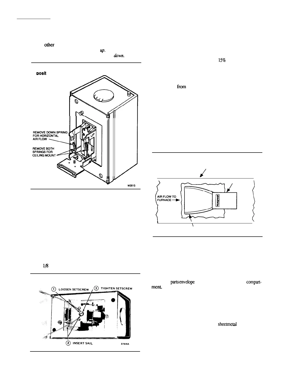
Ceiling-remove both springs.
All
orher
positions-leave in place the spring that is
attached to the bracket marked
up.
Remove the
spring
that is attached to the bracket marked
down.
Fig. 5-Adapting sail switch to F52 mounting
Dosit
ion.
MN15
MOUNT THE SWITCH (See special
instructions forF52)
The sail switch counterbalancing springs are calibrated
for proper operation when the sail switch case is mounted at
true level for horizontal air flow applications, or plumb for
vertical air flow applications. Proceed as follows, using the
mounting template provided.
1. Mount the template at desired location. BE SURE
THAT THE ARROW INDICATING AIR FLOW POINTS
IN THE PROPER DIRECTION. Level the long dimension
shown on the template for horizontal mounting. Plumb this
dimension for vertical mounting.
2. Cut the hole indicated on the template in the ductwork.
3. Center punch the screw holes indicated and drill out
with a
lN
inch drill.
Fig. 6-Attaching sail to switch.
@
IN5ERT,A,L
3764A
4. Attach the
sail to the switch as shown in Fig. 6.
NOTE: The sail switch makes at about 250 fpm and breaks
at 75 fpm. In an average residential system that produces
500 fpm in the return air duct, the switch will make at
approximately 50% and break at
1570
of the maximum air
flow rate. In a system where air flow maybe as high as
1000 fpm the switch will not break until the airflow drops
to about 7.5% of maximum. To retain the original on-off
ratios of air flow, mm the sail. Trim about 1-1/2 in.
[38 mm]
horn
the sail for 1000 fpm air velocity and
proportionally more or less for higher or lower velocity.
Correct trimming is important. If sail is too long, it will
flutter and the wire frame may break prematurely; if it is
too short, the switch may not operate.
5. Press the sides of the wire loop together. Insert the sail
into the duct.
6. Before fastening the switch in position, check to make
certain air movement will operate the switch. In the off
position, the sail should point into the direction of airflow as
shown in Fig. 7.
Fig. 7-Position sail so it points into the
direction of airflow when switch is off.
/
DUCT
(
f
SAIL SWITCH
~
)
{-(
1
\
/
i
SAIL IN OFF POSITION:
POINTS INTO AIR FLOW
M301 O
7. Secure the switch by using the sheet metal screws
provided. After wiring, snap on the cover. The Honeywell
trademark tab can be snapped out and rotated 180 degrees so
it will be upright for any vertical mounting position.
MOUNT SAIL SWITCH ON THE F52
1. Remove the sail switch, L-shaped mounting bracket
and small
part.senvelope
from the air cleaner wiring
compart-
ment.
2. Remove sail switch coverandremoveknockout oppo-
site of the arrow stamped on the inside of the case.
3. Turn the air cleaner over and rest it on the carton.
4. Mount the sail on the sail switch.
5. Locate the two black wires extending from the back of
the power supply. Pull wires
through
L-shaped bracket and
case knockout. Using two tapered
sheetrnetal
screws from
the envelope, mount the L-shaped bracket to the air cleaner.
Next, remove the ground screw on the sail switch to prevent
interference with the L-shaped bracket. Mount the sail switch
to the L-shaped bracket with two 8-32 screws. Airflow
should be in opposite direction of airflow arrow.
4

 Loading...