EasyManua.ls Logo

Honeywell S9240F1004

Honeywell S9240F1004
28 pages
To Next Page IconTo Next Page
Loading...
INSTALLATION INSTRUCTIONS
69-2088-01
®
Automatic Ignition Systems
ANSI Z21.20
S9240F1004 Modulating Hot Surface
Ignition Integrated Furnace Control
APPLICATION
The S9240F1004 Integrated Furnace Control (IFC) is
designed specifically to work with a Lennox G71MPP variable
firing rate, high efficiency furnace. It provides gas ignition,
safety shutoff, and variable speed fan control with multi-firing
rate gas heating and up to 2-stage electric cooling
applications.
FEATURES
The S9240F1004 provides the following features:
Monitors a single stage or 2-stage conventional low
voltage thermostat for requests for heat, cool, or fan.
Monitors an input provided for connection to a
thermostat with a dehumidification output or Harmony
III Zone Control.
Provides three stage furnace input rate control when
operating with a conventional single stage thermostat.
Provides 2-stage or modulating furnace input rate
control based on field selected option when operating
with a conventional 2-stage thermostat.
Manages ignition of a main burner flame up to 400,000
BTU per hour using a 95 V hot surface igniter.
Monitors the appliance pressure, limit, and rollout
switches and generate control actions as
programmed.
Controls the 24 Vac Honeywell amplified gas/air gas
valve.
Controls a 3-phase 120 Vac inducer motor (Fasco
Model 92B1 or other with identical voltage/frequency
curve) and blower assembly based on heat demand
and other parameters.
Controls the Regal Beloit 3.0 ECM circulator motor and
blower based on defined appliance CFM profiles
and/or a discharge air sensor signal.
Controls single stage or 2-stage cooling equipment.
The outdoor unit is controlled directly by the 24 Vac
conventional thermostat inputs. The IFC manages the
circulator speed based on cool demand and other
parameters.
Controls a 120 Vac humidifier output and a 120 Vac
EAC output.
Operates with 120 Vac single phase, 60 Hz power
supply.
Uses a 7-segment LED display to communicate error
code and status information. A single on board button
is provided to generate the desired information
display.
Provides field selectable DIP switches to select field
specific control operating parameters such as type of
thermostat, delay timings, and fan operating
parameters.
Provides on-board jumpers that can be clipped to
permanently enable 2-stage cooling, heat pump
compatibility, dehumidification sequences, and define
appliance characteristics for field replacement
purposes.
Provides Field Test Mode and Diagnostic Recall Mode
to assist the installation/service technician.
Stores the 10 most recent error codes, which are
accessible by the service technician in Diagnostic
Recall Mode.

Questions and Answers:

Honeywell S9240F1004 Specifications

General IconGeneral
BrandHoneywell
ModelS9240F1004
CategoryControl Unit
LanguageEnglish

Summary

APPLICATION

INSTALLATION INSTRUCTIONS

SPECIFICATIONS

Electrical Ratings

Details voltage, current, and frequency ratings for the IFC.

Timings

Lists operational delays and durations for various furnace functions.

LED

Describes the 7-segment LED display for status and error communication.

Operating

Specifies operating temperature, storage temperature, and humidity limits.

Approvals

Lists certifications like CSA and ANSI Z21.20.

INSTALLATION

Location

Describes the recommended mounting location within the furnace for optimal access and environmental conditions.

Mounting

Details the procedure for physically attaching the IFC to the appliance mounting panel.

Wiring

Provides general guidance for connecting wires to the IFC, emphasizing compliance with diagrams and codes.

Jumpers

SETTINGS AND ADJUSTMENTS

DIP Switch S1 Settings

Configures thermostat selection, stage delays, and fan delays using DIP switch S1.

DIP Switches

Introduces the three DIP switch blocks (S1, S2, S3) for system configuration.

DIP Switch S2 Settings - Cooling Airflow

DIP Switch S3 Settings - Heating Airflow

CHECKOUT

Check Normal Operation

Outlines the steps to verify normal system operation after installation or maintenance.

Pressure Switch Calibration

Explains the mandatory calibration process for establishing furnace operating parameters.

Light Off

Describes the initial IFC self-check and verification of no main burner flame.

Fan Mode

Describes how the IFC controls the circulator fan based on thermostat requests.

Normal Heat Mode - Conventional 2-Stage Thermostat

Lennox Modulating Mode - Conventional 2-Stage Thermostat

Normal Heat Mode - Conventional Single Stage Thermostat

Single Stage Cooling

Two Stage Cooling

Ignition Retry

Ignition Recycle

Rollout Circuit Operation

Limit Switch Circuit Operation

Low Pressure Switch Operation

High Pressure Switch Operation

Hot Surface Igniter (HSI) Control

Humidity Control

Line Voltage Humidifier

Explains the conditions for energizing the line voltage humidifier output.

Low Voltage Humidifier

Details the connection and energization of a 24 Vac humidifier.

Standard Dehumidification

Describes enabling standard dehumidification via a jumper and DS terminal connection.

Harmony III Operation

Explains IFC operation with Harmony III zone control, using a jumper and DS signal.

Electronic Air Cleaner

Error Conditions

Main Valve Sensing

Describes IFC response to issues with main valve voltage detection and relay contacts.

Flame Out of Sequence

Details IFC reaction when flame is sensed unexpectedly or for too long.

Line Voltage Sensing

Explains IFC monitoring of line voltage for regulation and potential lockout.

Weak Flame Sensing

Describes IFC behavior when a weak flame signal is detected for an extended period.

Hot Surface Igniter (HSI) Sensing

Details IFC response to open-circuited HSI or failed ignition circuitry.

Resets

Indoor Blower Motor Failure

Inducer Motor Failure

Check Safety Shutoff Operation

Operating Sequences

TROUBLESHOOTING

LED User Interface

Describes the 7-segment LED and pushbutton for system status and diagnostic access.

Pushbutton

Explains how to use the pushbutton to navigate menu options like Idle, Diagnostic Recall, and Field Test.
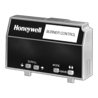
Field Test Mode

Gas Heat Display - System Status

Compressor HeatingCooling Display - System Status

LED Error Codes

Related product manuals