EasyManua.ls Logo

Honeywell satronic DMG 971 User Manual

Honeywell satronic DMG 971
6 pages
To Next Page IconTo Next Page
Page #1 background imageLoading...
Page #1 background image
1
A Honeywell Company
certified Qualitysystem
ISO 9001 / EN 29001
Reg. Nr. 10529
INTRODUCTION
The burner control box DMG 971 controls and supervises
power burner for gas and dual fuel. The control box is
approved and certified according the relevant European
standards. The use on direct air heaters according DIN 4794
is also possible.
The microprocessor- based programming sequence ensu-
res extremely stable timings independent of voltage varia-
tions, ambient temperature and/or switch-on cycles. The
built-in information system not only provides a continuous
monitoring of the actual state of the box (very helpful es-
pecially for monitoring the start-up phase) but also informs
about the cause of a possible lock out. The lock out cause
is stored in such a way that it can be retrieved even after a
power failure.
The control box is designed for maximum safety in case of
fluctuations in the voltage supply. If the mains voltage drops
below the permitted level, operation is interrupted and the
control box automatically prevents the start sequence from
being repeated. In this way, the safety of the system is not
put at risk by a drop in the mains voltage. This low-voltage
protection works not only during start-up but also perma-
nently during operation.
CONSTRUCTIONAL FEATURES
Microprocessor, electronic components, output relais and
flame amplifier are placed on two printed circuit boards.
These plus the lockout- and reset circuit are well protected
inside a flame resistant, plug-in type plastic housing.
The reset switch for reset / remote lockout with its built-in
LED for displaying the information system plus the central
fixing screw are placed on top of the housing.
The wiring base S98 is equipped with spare- and
extraterminals and allows together with a variety of cable
entry points utmost flexibility of electrical wiring.
The DMG 971 is funstionally compatible to MMI 811 and
MMI 811.1
Please note: Is the DMG 971 to be used to
replace the MMI 811 or 811.1, care has to be
taken to make sure the air proving switch (LW) is
wired between terminals 4 and 7 and not like on
the MMI between 5 and 7.
DMG 971
Gas Burner Safety Control
For 2-stage forced draught and combi
oil/gas burners
Possible flame detectors:
- Ionisation probe
- Infrared flicker detector 1020
- UV flame sensor UVD 971
TECHNICAL DATA
Operating voltage 220 / 240 V (-15... +10%)
50 Hz ( ±5%)
Fuse rating 10 A fast, 6 A slow
Power consumption ca. 15 VA
Max. load per output
- term. 3 ignition trafo 1.5 A, cos ϕ 0.2
- term. 4 motor 2.0 A, cos ϕ 0.4
- term. 5 + 6 solenoid valves 1.0 A, cos ϕ 0.4
- term. B alarm indicator 1.0 A, cos ϕ 0.4
total load 5.0 A, cos ϕ 0.4
max. 10 A during 0.5 sec
Air proving switch 1 working contact 4 A, 230V
Stray light monitoring 5 sec
Sensitivity (operation) 1 µA
Min. required ion. current 1.5 µA
Sensitivity for stray light 0.4µA
Ionisation probe insulation Probe - earth
greater than 50 M
stray capacity Probe - earth
less than 1000 pF
cable lenght < 3 m
Flame detectors
IRD 1020 side-on or end-on viewing
UVD 971 end-on viewing
Weight incl. Wiring base 190 g
Mounting position any
Protection class IP 40
Approved ambient parameter
for control and flame detector max. 95% at 30° C
- for operation -20° C... +60° C
- for storage -20° C... +80° C
Build-up of ice, penetration of water and condensing
water are inadmissible
Approvals according
to European standards EN 298 and EN 230, as
well as all other relevant
Directives and standards
Classified acc. to EN 298 FTLLXN
Timings (sec.)
0737.11-00-e/01/99
Model waiting time max. reaction time for supervised pre-ignition ignition time Stray light safety time delay
start air proving switch pre-purge time time total monitoring 2nd-stage
tlw tv1 tvz tz tf ts tv2
01 0 60 24 3 5 5 3 12.5
Question and Answer IconNeed help?

Do you have a question about the Honeywell satronic DMG 971 and is the answer not in the manual?

Honeywell satronic DMG 971 Specifications

General IconGeneral
BrandHoneywell
TypeDMG 971
CategoryControl Unit
Frequency50-60 Hz
Protection ClassIP40
Flame detectorIR
ApplicationIndustrial burners
Operating Temperature-20°C to +60°C
Storage Temperature-40... +85 °C
Relative Humidity95% non-condensing
Weight0.5 kg
Input Voltage220-240V

Summary

Introduction

Constructional Features

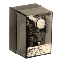
Describes the physical build, components, and housing of the control box, emphasizing protection and ease of use.

Technical Data

Details electrical, operational, and environmental specifications for the DMG 971 control box and flame detectors.

Application Features

Information System

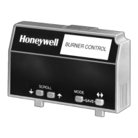
Explains the microprocessor-based system that monitors burner control operation and flame supervision via flash codes.

Programming Sequence Display

Details how the built-in microprocessor displays individual phases of the programming sequence using flash codes.

Lock-out Diagnoses

Describes how the system indicates error causes via flash codes when the unit is locked out, aiding fault finding.

Flame Detection

Outlines suitable flame detectors, including ionization probes, IRD 1020, and UVD 971, and their installation requirements.

Stray Light Monitoring

Explains the check performed at the end of the pre-purge time to detect stray light interference with flame sensing.

Lock Out and Reset

Low-Voltage Protection

Details how the control box monitors mains voltage to prevent operation below a safe threshold and prevent restart on low voltage.

Safety

States that the design and control sequence comply with applicable standards and regulations for safe operation.

Mounting and Electrical Wiring

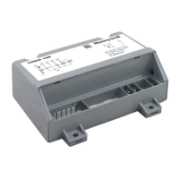
Provides information on wiring base terminals and general advice on connecting the control box and detector probes.

Installation Instructions and Maintenance

Important Notes

Lists critical precautions for installation by qualified personnel, wiring checks, fuse ratings, and safety device handling.

Function Control

Details procedures for testing the flame detection system on commissioning and after service, including start-up sequences.

Fault Finding

Describes how the information system aids troubleshooting during start-up or operation, listing common errors and possible causes.

Circuit and Timing Diagram DMG 971

IRD-OR UVD Connection

Illustrates the specific wiring connections for the IRD 1020 and UVD 971 flame detectors to the control box terminals.

Block Diagram DMG 971

Presents a block diagram showing the internal components of the DMG 971 and their interconnections for control and monitoring.

DMG 971 and Socket

Ordering Information

Lists available items, their designations, and item numbers for the DMG 971 control box, sockets, and related accessories.

Related product manuals