SHK(C)8M(2)
: Wireless Shock Sensors - Installation Instructions (ENGLISH)
Intr
oduc
tion
Th
e
S
H
K
8
M
s
e
r
i
e
s
i
s
d
e
s
i
g
n
e
d
t
o
p
r
o
t
e
c
t
w
i
n
d
o
w
a
n
d
d
o
o
r
s
u
r
r
o
u
n
d
i
n
g
s
,
a
n
d
i
s
u
s
e
d
t
o
d
e
t
e
c
t
f
o
r
c
i
b
l
e
a
t
t
a
c
k
u
p
o
n
t
h
e
s
u
r
f
a
c
e
o
n
w
h
i
c
h
i
t
i
s
m
o
u
n
t
e
d
.
I
t
i
s
c
a
p
a
b
l
e
t
o
d
e
t
e
c
t
2
d
i
f
f
e
r
e
n
t
t
y
p
e
s
o
f
f
o
r
c
i
b
l
e
a
t
t
a
c
k
s
:
-
S
t
r
o
n
g
a
t
t
a
c
k
:
t
h
e
d
e
v
i
c
e
w
i
l
l
s
e
n
d
a
n
a
l
a
r
m
f
o
r
a
n
y
s
i
n
g
l
e
s
h
o
c
k
e
v
e
n
t
w
h
o
s
e
i
n
t
e
n
s
i
t
y
e
x
c
e
e
d
t
h
e
f
a
c
t
o
r
y
s
e
t
s
t
r
o
n
g
a
t
t
a
c
k
s
e
n
s
i
t
i
v
i
t
y
l
e
v
e
l
.
-
R
e
p
e
a
t
e
d
a
t
t
a
c
k
s
:
t
h
e
d
e
v
i
c
e
w
i
l
l
s
e
n
d
a
n
a
l
a
r
m
a
f
t
e
r
a
d
e
f
i
n
e
d
n
u
m
b
e
r
(
c
o
n
t
r
o
l
l
a
b
l
e
)
o
f
c
o
n
s
e
c
u
t
i
v
e
s
h
o
c
k
s
,
w
h
o
s
e
i
n
t
e
n
s
i
t
y
e
x
c
e
e
d
t
h
e
f
a
c
t
o
r
y
s
e
t
r
e
p
e
a
t
e
d
a
t
t
a
c
k s
e
n
s
i
t
i
v
i
t
y
l
e
v
e
l
,
h
a
s
b
e
e
n
d
e
t
e
c
t
e
d
w
i
t
h
i
n
a
p
e
r
i
o
d
o
f
8
s
;
Th
i
s
d
e
v
i
c
e
i
s
i
n
t
e
n
d
e
d
f
o
r
u
s
e
w
i
t
h
a
w
i
r
e
l
e
s
s
a
l
a
r
m
s
y
s
t
e
m
t
h
a
t
s
u
p
p
o
r
t
s
t
h
e
A
L
P
H
A
o
r
V
2
GY
w
i
r
e
l
e
s
s
p
r
o
t
o
c
o
l
e
s
s
u
c
h
a
s
D
o
m
o
n
i
a
l
,
G2
,
D
i
m
e
n
s
i
o
n
,
L
y
n
x
a
n
d
Vi
s
t
a
c
o
n
t
r
o
l
p
a
n
e
l
s
.
The
SH
K
8
M
s
e
r
ie
s
Th
i
s
s
e
r
i
e
s
c
o
n
s
i
s
t
s
o
f
t
h
e
f
o
l
l
o
w
i
n
g
s
e
n
s
o
r
s
:
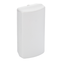
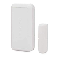
S
H
K
8
M
:
W
i
r
e
l
e
s
s
s
h
o
c
k
s
e
n
s
o
r
,
w
h
i
t
e
.
S
H
K
8
M
2
:
B
r
o
w
n
v
e
r
s
i
o
n
o
f
t
h
e
S
H
K
8
M
.
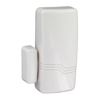
S
H
K
C
8
M
:
W
i
r
e
l
e
s
s
s
h
o
c
k
s
e
n
s
o
r
f
e
a
t
u
r
i
n
g
a
d
o
o
r
c
o
n
t
a
c
t
f
u
n
c
t
i
o
n
a
l
i
t
y
N
o
t
e
:
f
o
r
t
h
i
s
s
e
n
s
o
r
t
h
e
g
a
p
b
e
t
w
e
e
n
t
h
e
c
o
n
t
a
c
t
a
n
d
t
h
e
m
a
g
n
e
t
s
h
o
u
l
d
b
e
l
e
s
s
t
h
a
n
1
0
m
m
S
H
K
C
8
M
2
:
B
r
o
w
n
v
e
r
s
i
o
n
o
f
t
h
e
S
H
K
C
8
M
.
Ta
mpe
r
Switc
he
s
The
S
H
K
8M
f
eat
ur
es
t
w
o
t
a
m
p
er
s
w
it
c
hes
t
o
det
ec
t
dev
ic
e
ope
ning
and
w
r
enc
h
o
f
f
f
r
o
m
it
s
mount
ing
s
ur
f
a
c
e
A
r
e
a
of Shoc
k
Pr
ote
c
tion
The
S
H
K
8M
c
an
det
ec
t
s
h
oc
k
s
w
it
hin
a
r
adius
o
f
2.
5
m
.
This
c
a
n
v
ar
y,
de
pending
on
t
he
t
y
pe
of
mou
nt
i
n
g
s
ur
f
ac
e.
S
ee
Figur
e
1.
R
e
gis
te
r
ing
the
Se
ns
or
a
t the
Contr
ol
P
a
ne
l
E
ac
h
s
ens
or
in
t
he
S
H
K
8
M
s
er
ies
h
as
a
unique
,
f
a
c
t
or
y
-
s
et
s
er
ial
numbe
r
t
ha
t
mus
t
be
r
egis
t
e
r
ed
at
t
he
c
ont
r
ol
panel
bef
or
e
it
c
an
be
us
ed
by
t
he
s
y
s
t
em.
N
o
t
e
t
hat
t
he
bat
t
er
y
mus
t
be
ins
t
alled
bef
or
e
r
egis
t
r
a
t
ion
.
W
h
en
r
egis
t
er
ing,
n
ot
e
t
he
f
o
ll
o
w
ing:
1.
R
e
m
o
v
e
t
he
c
ov
er
of
t
he
s
ens
o
r
.
S
ee
Figur
e
2.
2.
S
et
S
W
4
t
o
OFF
(
T
es
t
Mode
dis
a
bled)
.
3.
I
ns
t
all
t
he
ba
t
t
er
y
in
t
he
holder
p
r
ov
ided.
S
ee
Figur
e
3
.
4.
T
o
r
egis
t
er
,
t
r
ans
mit
f
r
om
t
he
un
it
w
he
n
p
r
ompt
ed,
b
y
ac
t
iv
at
i
n
g
it
s
t
amper
s
w
it
c
h
as
f
ollow
s
:
D
epr
es
s
t
he
c
ov
er
t
amper
s
w
it
c
h
light
l
y
f
or
s
ev
er
al
s
e
c
ond
s
,
t
hen
op
en
it
.
Th
e
pan
el
be
eps
t
o
c
on
f
ir
m
r
eg
is
t
r
at
ion.
5.
Ver
if
y
t
he
s
t
r
en
gt
h
of
t
he
s
ignal
r
ec
eiv
e
d
a
t
t
h
e
c
ont
r
o
l
pan
el
(For Domonial, G2 an
d Dimensi
o
n only ).
Mount
i
n
g
1. Remove the cover of the sensor. See Figure
2.
2
. Mo
u
nt th
e ba
ck
casing on a
solid sur
fa
ce using
th
e screws
su
pp
lie
d in th
e
th
re
e
mou
nting h
oles. S
ee
F
igu
re
4.
For S
HK
C8M o
n
l
y,
mo
un
t th
e
ma
g
n
e
t (su
p
plied
) ad
jacent
to
the mounting plate
’s
a
lignme
nt strip
.
See Fig
ure
3.
3
. Replace t
he
cover
.
Note: A
void installing the
magn
et on a metallic surf
ace
, such as
a
metal door frame.
Sensi
t
ivity Configuration
The
sensitivity of the
de
vice can be adjusted. The
re are 2 ways to
control the
sen
sitivity:
- Gross: Select w
ith SW1
betw
een High/lowse
nsitivity
- Fine: Adjust the sensitivity using the potentiometer.
In order to verify the correct setting, enter test mode and tap at
the required point within the coverage area shown in figure 1 –
the LED will light up if the threshold is passed.
Note: after any setting change of the DIP switch, device must be
restarted: remove battery, wait 10 seconds, and insert it again to
power on device.
Pulse Count Configuration
The pulse count is the number of shocks required to trigger an
alarm in case of repeated attack. To configure the pulse count of
the device, you must enter LEARNING MODE.
1. To enter Learning Mode, power on the sensor with SW 3 in
the ON position (see Figure 5):
2. Wait for 10 seconds, until the red LED lights. You will then
have 30 seconds to register the pulse count.
3. Start tapping the area of coverage – while the red LED is ON.
Each valid impact will turn the LED OFF for 500ms then
it will return to ON.
The pulse count is automatically determined by the number
of valid impacts made to the area to be protected There is no
limit to the number of taps allowed. We recommend to tap
the area furthest away from the location of the detector.
If the LED doesn’t go off, the area is out of coverage
range or the impact level is lower than required and the
shock was not taken into account. Try again using a higher
sensitivity.
After the 30 seconds the LED will flash to confirm the
number of pulse counts.
4. By default, the pulse count is set to 10. To restore the default
pulse count, repeat the procedure described in point 1,
without registering any shocks during the period of 30s after
the red LED has lit.
At the end of this period, the LED will flash 10 times to
confirm that the default pulse count has been restored.
The learn result will be stored into flash memory and will remain
unchanged until the next learning.
Note: In order to calibrate the sensor precisely, you can use the
Viper calibration tool
device preset to 6 kg/cm
2
constant level of
shock to frame - never use directly on glass - For areas larger
than 2.5m, it is recommended to use two sensors, in order to
ensure optimal coverage
(Ref: PC.06138.00, not supplied).
Test Mode
Use Test Mode to check the configuration and settings of the
sensor. If Learning Mode is disabled or finished and Test Mode
has been enabled (SW 4 in the ON position), the module enters
Test / Installation Mode. In Test Mode:
■ The sensor detects the shock, tamper and contact alarm, as
normal.
■ The LED will indicate an alarm.
■ No RF message will be transmitted
■ Test Mode will be exited after 2 minutes.
Figure 1 on page 3 shows how to use the calibration tool to test
that the sensor is functioning correction. Each shock registered
causes the LED to light.
Power
The sensor signals a battery failure at the control panel when the
battery needs to be replaced. The sensor will continue to operate
for up to one week after this.
Replace battery with 3V Lithium
battery only.
- 1 -