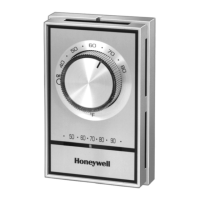
T410A,B ELECTRIC HEAT THERMOSTATS
68-0145—2
4
Helping You Control Your World
68-0145—2 C.H. Rev. 4-96 Printed in U.S.A.
Home and Building Control
Honeywell Limited-Honeywell Limitée
155 Gordon Baker Road
North York, Ontario
M2H 2C9
Home and Building Control
Honeywell Inc.
1985 Douglas Drive North
Golden Valley, MN 55422
Printed on recycled paper containing at
least 10% post-consumer paper fibers.
Prebend and push solid wires into the outlet box.
Remove the thermostat cover by grasping the top and
bottom cover edge and pulling it outward away from the
thermostat base.
Turn the temperature setting dial so the setpoint
indicator is at the 12 o’clock position to prevent
damaging the dial stop.
Mount the thermostat on the outlet box. Tighten the two
mounting screws (included) to secure the thermostat,
taking care to avoid excessive pressure on the setting
dial. See Fig.4.
SETTINGS AND CHECKOUT
Setting
The thermostat temperature setting can be adjusted by
turning the setting dial clockwise or counterclockwise to the
desired setting. See Fig. 5. To determine appropriate setting,
allow the thermostat to operate for several hours.
Checkout
IMPORTANT
Make sure all wiring connections are tight before
proceeding with Checkout.
Check out thermostat operation as follows:
Turn the setting dial fully clockwise; heating circuit
makes and electric heater starts.
Turn the setting dial fully counterclockwise; the heating
circuit breaks and the heater starts to cool.
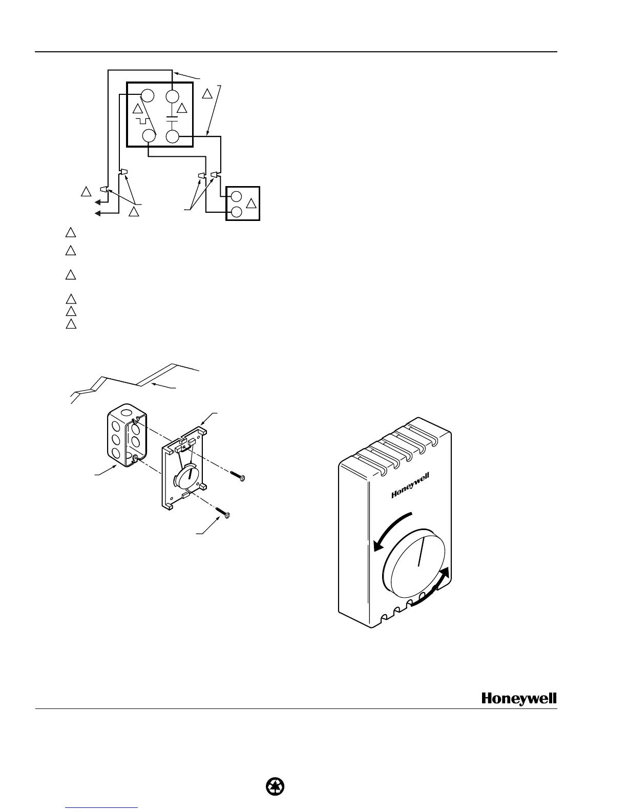
M5812B
L1
(HOT)
L2
1
2
4
SOLDERLESS
CONNECTORS
POWER SUPPLY. PROVIDE DISCONNECT MEANS AND
OVERLOAD PROTECTION AS REQUIRED.
USE SPECIAL SERVICE CO/ALR SOLDERLESS CONNECTORS
WHEN CONNECTING ALUMINUM CONDUCTORS OR A FIRE
HAZARD MAY RESULT.
BREAKS AT POSITIVE OFF AND REMAKES UNDER –31°F (–35°C);
NORMALLY THERMALLY ACTIVATED. BREAKS ON TEMPERATURE
RISE; MAKES ON TEMPERATURE FALL.
USE A SEPARATE LIMIT CONTROL IN THE HEATING APPLIANCE.
BREAKS AT POSITIVE OFF ONLY; NOT THERMALLY ACTIVATED.
DO NOT CONNECT GROUNDED CONDUCTOR (NEUTRAL) ON
120 OR 227V CIRCUITS. INSULATE AND TAPE OR CUT OFF
RED WIRES IF UNUSED.
1
2
3
4
5
6
ELECTRIC
HEATER
RED
WIRE
6
T410B
L1
T1
5
L2
T2
3
Fig. 4. Mounting thermostat on outlet box.
New Applications
Disconnect power supply to prevent electrical shock or
equipment damage. All wiring must comply with local
electrical codes and ordinances.
Run line voltage wiring to the thermostat location.
Do not remove the T410 Thermostat Cover. Using wire
connectors approved for No. 12 wires, make line
voltage connections directly to the leadwires on the
thermostat. See Figs. 2 and 3 for typical wiring
connections.
WALL
MOUNTING
SCREWS (2)
M5803
OUTLET
BOX
THERMOSTAT
BASE
M5804
•
4
0
•
5
0
•
6
0
•
7
0
•
8
0
•
˚F
TURN SETTING DIAL
CLOCKWISE OR COUNTER-
CLOCKWISE TO ADJUST
TEMPERATURE SETTING.
Fig. 3. Typical wiring connections for T410B.
Fig. 5. Adjusting temperature setpoint.
www.honeywell.com/yourhome
 Loading...