2
2
6
4
1
1
2
3
4
5
6
1
L1
L1
L2
T2
T1
T1
3
3
5
SOLDERLESS
CONNECTORS
SOLDERLESS
CONNECTORS
L1
(HOT)
L2
L1
(HOT)
L2
ELECTRIC
HEATER
ELECTRIC
HEATER
RED
WIRE
Disconnect power supply before making wiring connections
to prevent electrical shock or equipment damage.
All wiring must comply with applicable codes
and ordinances.
Thermostats are designed to be used with a limit control in
the appliance.
TO CONNECT WIRES:
Make line voltage wiring connections directly to the lead-
wires installed on the thermostat using wire connectors
approved for No. 12 wires.
When using aluminum conductors, all wiring connections
to this thermostat must be made to the factory installed lead-
wires, using approved CO/ALR solderless connectors.
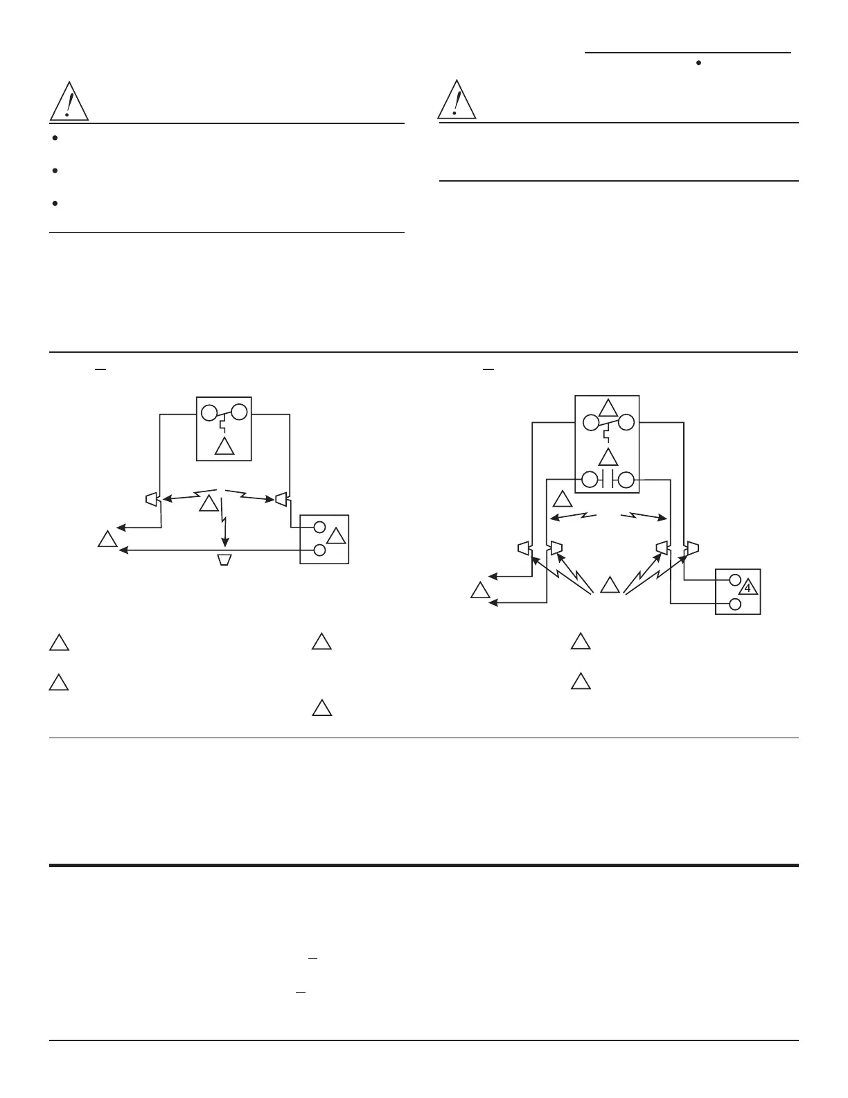
Fig. 2 Typical hookup for a T498A thermostat. Fig. 3 Typical hookup for a T498B thermostat.
POWER SUPPLY. PROVIDE DISCONNECT MEANS
AND OVERLOAD PROTECTION AS REQUIRED.
SPECIAL SERVICE CO/ALR SOLDERLESS
CONNECTORS MUST BE USED WHEN
CONNECTING ALUMINUM CONDUCTORS;
OTHERWISE. A FIRE HAZARD MAY RESULT.
BREAKS AND REMAKES BELOW
- 31°F [-35C], OTHERWISE THERMALLY
ACTIVATED: BREAKS ON TEMPERATURE RISE,
MAKES ON TEMPERATURE FALL.
THERMOSTATS ARE DESIGNED TO BE USED WITH
A LIMIT CONTROL LOCATED IN THE APPLIANCE.
BREAKS AT POSITIVE OFF ONLY,
NOT THERMALLY ACTIVATED.
DO NOT CONNECT GROUNDED CONDUCTOR
(ie neutral) ON 120 OR 277V CIRCUITS.
INSULATE AND TAPE, OR CUT OFF RED WIRES
IF UNUSED.
CAUTION
CAUTION
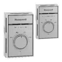
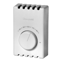
T498A, B Electric Heat Thermostat
INSTALLATION OPERATION
Setting and Checkout
IMPORTANT:
After the thermostat has been installed and wired, simulate
normal operation as follows:
1. Turn setting dial all. the way clockwise electric heater
should start to heat.
2. Turn dial all the way counterclockwise the power circuit
should be broken and the electric heater should start to cool.
Be sure that all wiring connectors are tight.
3. To determinate final setting, begin with dial indicator at
20°C [70°F] on the scale. After at least 2 hours operation,
if this setting is not satisfactory, turn dial indicator upscale
to raise the temperature, or downscale to lower the
temperature. Move indicator only a few degrees each time
an adjustment is necessary.
3
 Loading...