T6570, T8570 SERIES DIGITAL FAN-COIL THERMOSTATS
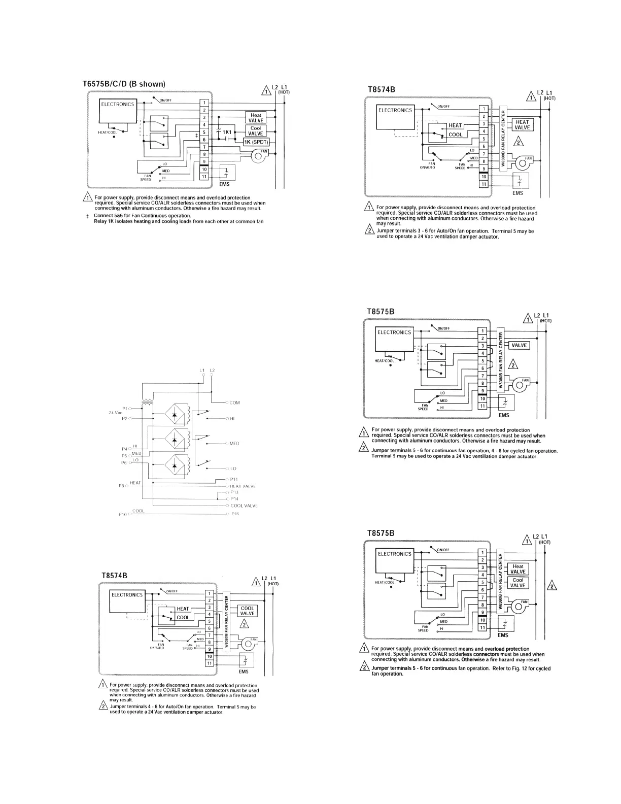
Fig. 13. Wiring 4-pipe, heat/cool with manual heat/cool
changeover switch, cycled fan, using external relay.
Fan-Relay Control Center
T8570 thermostats are typically used with load relays to switch
line voltage loads. Honeywell offers a convenient fan-relay
center, the W6380, that provides 24 Vac power, three
interlocked fan relays, and wiring center terminations for valve,
relay and contactor loads. The W6380 schematic can be found
in Fig. 14.
Fig. 16. Wiring 2-pipe 24V heat thermostat with fan On/
Auto switch.
Fig. 17. Wiring 2-pipe heat/cool with manual heat/cool
changeover switch, continuous or cycled fan.
Fig. 14. W6380 wiring diagram.
Fig. 15. Wiring 2-pipe, 24V cool-only thermostat with fan
On/Auto switch.
Fig. 18. Wiring 4-pipe 24V heat/cool with manual heat/cool
changeover switch, continuous fan.
9 95C-10897–6
 Loading...