2
APH07CH04
-
R2000EN
Mechanical design
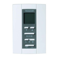
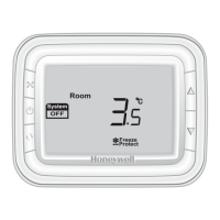
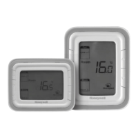
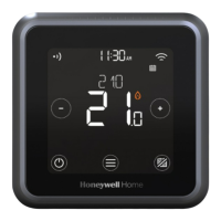
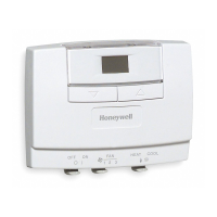
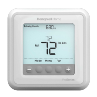
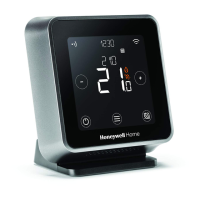
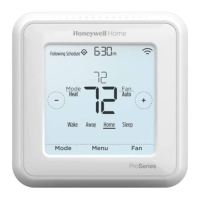
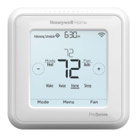
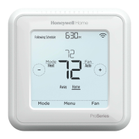
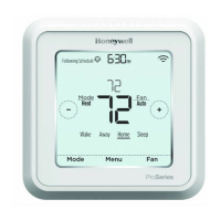
Thermostat appearnce
Function
Temperature display
The displayed temperature can be set to acquired room
temperature or setpoint. The setting can be made during
Installer Set-Up process.
Keypad lock
Keypad lock can be set in ISU with default status is all
keys available. You may change into all buttons locked
out.
Ventilation mode
Press mode button to enter ventilation mode. In
ventilation mode, no output for valve while the fan will
operate according to selected fan speed.
Technical specification
Power supply T6811DP08: 110(+20%,-10%)VAC
T6812DP08: 220(+/-10%)VAC
Frequency 50/60Hz
Input Current 4(2)A
Control algorithm PI, On/off output
Accuracy +/-1
o
C at 21
o
C
Rating capacity 220V: 4(2)A for fan load, 2(1)A for
zone valve;
110V: 4(2)A for fan load, 2(1)A for
zone valve
Cycle times 100,000
Setpoint range 10~32
o
C
Installation Installed on 86×86mm junction
box or US2×4 inch.
Protection Class IP20
Environmental Operation temperature -18~49
o
C
Conditions Shipping temperature -35~65
o
C
Relative humidity 5~90%
Action Type Action Type 1
Maximum 155
o
C
Temperature
for Relay Wiring
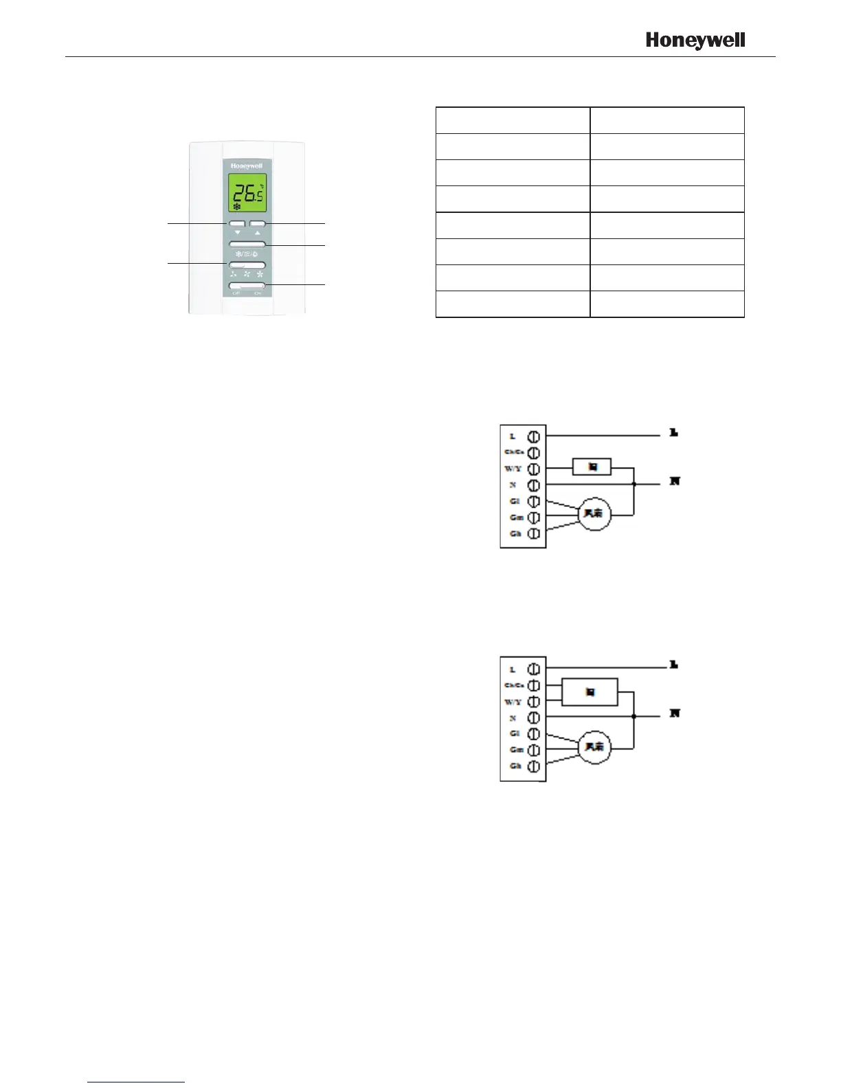
Terminal Designations
Terminal Description
L
Line Voltage Power
Ch/Cc
Heating close/Cooling close
W/Y
Heating open/Cooling open
N
Line Voltage Ground
Gl
Low speed fan
Gm
Medium speed fan
Gh
High speed fan
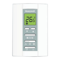
DOWN BUTTON
FAN BUTTON
UP BUTTON
MODE BUTTON
POWER BUTTON
Wiring diagrams
Typical wiring for ON/OFF control in 2 pipes Heat/Cool/
1H1C (VC4013)
Typical wiring for ON/OFF control in 2 pipes Heat/Cool/
1H1C (VC6013)
 Loading...