T775L SERIES 2000 ELECTRONIC STAND-ALONE STAGING CONTROLLER
29 62-0257—11
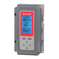
Fig. 70. Program - Setpoint Offset (Loop 2 only).
Fig. 71. Reset Curve with Offset for Loop 2.
3.4. Loop 2
For the second loop (if it is configured for Reset), the
Offset parameter displays on the Program menu as
shown in Fig. 70.
3.4.1. SETPOINT OFFSET (Loop 2 only)
This value is the number of degrees plus (+) or minus (-)
that you want the temperature to be offset from the Loop 1
setpoint. See Fig. 71. For example, If you want the Loop 2
setpoint to be 10°F less than the Loop 1 setpoint, enter
-10°F.
1. From the menu, use the and buttons to
highlight OFFSET.
2. Press the button to display the value.
3. Use the and buttons to increase/decrease the
desired temperature.
OFFSET Default: 0°F
OFFSET Range: -150°F to 150°F (-101°C to 66°C)
4. Press the button to accept the value and display
the next option.
3.4.2. Loop 2 Programming
To complete the programming of Loop 2, perform the
procedures in “3.3.5. THROTTLING RANGE” through
“3.3.7. SETBACK OFFSET (if configured)” beginning on
page 28.
3.4.3. Exit Loop Programming with
Reset
When you finish programming the loop(s), press the
HOME button to leave programming mode and return to
the home screen.
If you have additional relays configured, continue with
“3.5. Program Menus for the Additional Relays with
Reset” on page 29.
If there are no additional relays, continue with “3.7. Exit
Programming with Reset” on page 31.
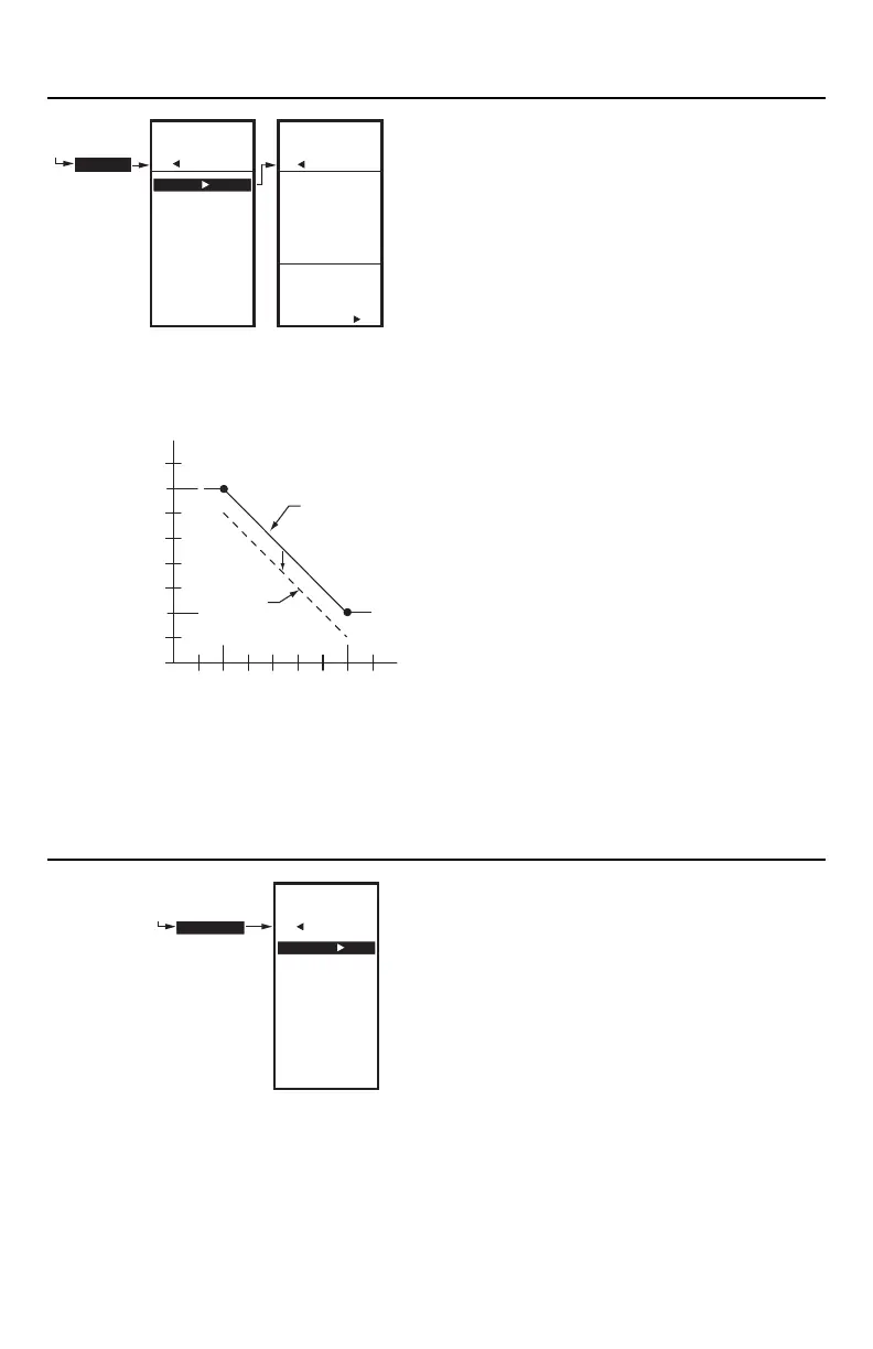
Fig. 72. Program Menus for Relays.
3.5. Program Menus for the Additional
Relays with Reset
Press the MENU button, select PROGRAM, then select
an available relay to view the parameters. Fig. 72 shows
the example for relay 9. If Relays are not set for Reset in
Setup mode, simply enter the setpoint desired.
Up to two additional two relays can be available for
independent on-off control. Examples of Loop and Relay
configurations are:
• Number of relays = 8. Loop 1 uses relays 1-3,
and Loop 2 uses relays 3-6. The remaining two
relays (7 and 8) are available for use.
• Number of relays = 11. Loop 1 uses relays 1-5,
and Loop 2 uses relays 6-10. The remaining
relay (11) is available for use.
• Number of relays = 12. Loop 1 uses relays 1-4,
and Loop 2 uses relays 5-8. Relays 9 and 10
are available for use, but in this case, relays 11
and 12 are not usable.
PROGRAM
LOOP 2
MENU
PROGRAM
LOOP 2
OFFSET
-10
F
o
ENTER
SETPOINT
OFFSET
FOR
LOOP 2
M24410
MENU
PROGRAM
LOOP 2
OFFSET
THROT RNG
HEAT/COOL
SETBACK
EXIT
SENSOR B
SP MAX A1
(BOILER MAX)
SP MIN A2
(BOILER MIN)
200
140
10
LOOP 2
SETPOINT
OFFSET
-10°F
190
20
30 40 50 60
70
°F80
150
160
170
210
220
180
°F
RESET B1
(OUTSD MIN)
RESET B2
(OUTSD MAX)
S
E
N
S
O
R
A
M24403
LOOP 1
SETPOINT
OFFSETDIFFRNTL
DIFFERENTIAL
SENSOR
HEAT/COOL
SETBACK
EXIT
PROGRAM
RELAY 9
MENU
PROGRAM
RELAY 9
M24414
 Loading...


