T775L SERIES 2000 ELECTRONIC STAND-ALONE STAGING CONTROLLER
62-0257—11 6
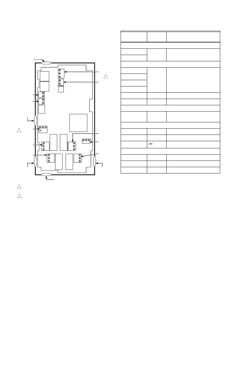
Controller Wiring Details
The wiring connection terminals are shown in Fig. 7 and
are described in Table 2 on page 6.
See Fig. 8 – Fig. 12 beginning on page 7 for typical T775L
wiring applications.
Fig. 7. T775L Terminal and Feature Locations.
NOTE: Relays 5–8 are assigned to the first T775S
Expansion Module, if connected. Relays 9–12
are assigned to the second T775S, if connected.
WIRING APPLICATION
EXAMPLES
Fig. 8 – 12 beginning on page 6 illustrate typical controller
wiring for various applications.
NOTE: The electronic Series 90 output provided with
modulating T775 models can not drive electro-
mechanical slidewire devices like older Series 3
modulating meters (prior to Series 6), V9055s,
and S984s.
C
NO
NC
C
NO
NC
C
NC
NO
C
NC
NO
T
T
T
T
+
–
+
–
SENSOR A
SENSOR B
KNOCKOUT A
DIGITAL INPUT
POWER
120/240 VAC
OUTPUT
RELAY 2
KNOCKOUT D
POWER
24 VAC
OUTPUT
RELAY 1
KNOCKOUT C
KNOCKOUT E
SENSORS A AND B USE THE TWO TT CONNECTIONS AND ARE
POLARITY INSENSITIVE.
A SEPARATE EARTH GROUND IS REQUIRED FOR ANY POWER
SOURCE (24, 120, OR 240 VAC).
1
1
2
M24383
OUTPUT
RELAY 3
T775 BUS
OUTPUT
RELAY 4
2
C
+
KNOCKOUT B
120
COM
240
Table 2. Description of Wiring Terminal Connections.
Connection
Terminal
Label Description
Sensors
Sensor A
T T
Temperature Sensor; polarity
insensitive
Sensor B
Outputs
Relay 1
NO
COM
NC
120-240 Vac Relay Output
Relay 2
Relay 3
Relay 4
Input
DI + - Digital Input (dry contact)
Interconnect
T775 BUS
+
-
Terminal Connection to/from
T775S
24 Vac Power
24V + + 24 Vac Hot
Common - 24 Vac Common
Ground
Earth Ground
a
a
A separate earth ground is required for all installations
regardless of the power source (24, 120, or 240 Vac).
120 or 240 Vac Power
120 Vac 120 120 Vac Power
Common COM Common
240 Vac 240 240 Vac Power
 Loading...


