T775L SERIES 2000 ELECTRONIC STAND-ALONE STAGING CONTROLLER
11 62-0257—11
Setpoint High Limit
You can set an irreversible setpoint high limit maximum
value for any single displayed setpoint value.
Adjust the setpoint (at any output) to the desired
maximum setpoint. Then, simultaneously press the
HOME, , and buttons and continue to press all three
buttons for five seconds to set the setpoint high limit
maximum to this value.
NOTE: You must press all three buttons at exactly the
same time for this action to occur.
IMPORTANT
1. This action sets the maximum setpoint value of
all outputs to the setpoint high limit maximum.
2. Setting the high limit setpoint maximum is irre-
versible. If you perform the action inadvertently
and this setpoint adversely affects the control of
your system, you must replace the controller.
Staged Operation
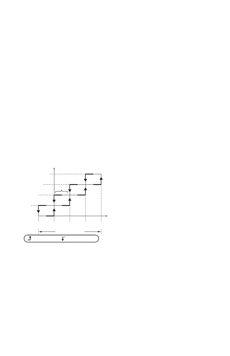
Staging occurs as illustrated in Fig. 18 for a Heat setpoint
of 200°F and a throttling range of 20°F when the Integral
value is zero (0). When the Integral is not zero, then the
actual temperatures at which stages energize and de-
energize will vary from this example; see “1.3.4.2.
INTEGRAL” on page 18.
NOTE: A non-zero integral causes the control to move
toward the setpoint value.
Fig. 18. Staging Behavior
(when effective Setpoint = 200°F).
Programming the T775L
Controller
In addition to the two staged loops, up to two additional
relays can be available for independent on-off control.
Examples of Loop and Relay configurations are:
• Number of relays = 8. Loop 1 uses relays 1-3, and
Loop 2 uses relays 4-6. The remaining two relays (7
and 8) are available for use.
• Number of relays = 11. Loop 1 uses relays 1-5, and
Loop 2 uses relays 6-10. The remaining relay (11) is
available for use.
• Number of relays = 12. Loop 1 uses relays 1-4, and
Loop 2 uses relays 5-8. Relays 9 and 10 are available
for use, but in this case, relays 11 and 12 are not
usable.
• Number of relays = 8. Loop 1 uses relays 1-6, and
Loop 2 uses relays 7-8. There are no additional relays
available for use.
IMPORTANT
If you change the number of relays, the control-
ler resets the number of relays per loop to zero
(0) for all loops. You must use Setup mode to
reconfigure all loops and additional relays. See
page 11.
To program the controller, perform the setup configuration
(see “1. Setup”) and then select one of the following
procedures depending on whether the Reset function is to
be used:
• Program the Outputs for No Reset — see
“2. Programming Output (Loops and Additional
Relays) with No Reset” on page 22.
• Program the Outputs for Reset — see “” on page 25.
When programming is complete, you may continue with
“4. Scheduling” on page 31.
1. SETUP
Setup provides the ability to change the factory default
settings for the temperature sensors and outputs, to
enable/disable reset control, and to enable/disable
scheduling.
IMPORTANT
If you change the number of relays, the control-
ler resets the number of relays per loop to zero
(0) for all loops. You must use Setup mode to
reconfigure all loops and additional relays.
NOTE: The T775L controller interface is intuitive. You
may want to use this procedure simply as a ref-
erence to locate the particular option or parame-
ter of interest.
NOTES:
1. If you press the HOME button or there is no
keypad activity for four minutes, you exit
Setup mode and return to the home screen.
2. If you press the MENU button, you exit Setup
mode and go to the Program menu.
Once in Setup mode, you use the —
• Left arrow button() to scroll backward through the
Setup menus
• Right arrow button () to select the highlighted menu
item and display its content
• Up and Down arrow buttons ( and ) to scroll up
and down through a list of items or to increase or
decrease the value of a displayed setup parameter
Setup Procedure
The Setup process uses a hierarchical menu structure
that is easy to use. You press the and arrow buttons
to move forward and backward through the menus.
NOTE: The menus can display only those relays that
are defined in Setup (see “1.3.1. Number of
RELAYS” on page 14). For example, if you con-
figure only two relays, then only two relays dis-
play on the appropriate menus.
M24297
THROTTLING RANGE
STAGE 2 ON
STAGE 3 ON
STAGE 1 ON
-25%
STAGES
HYST.
75%
205°F 185°F
0%
200°F
25%
195°F
STAGE 4 ON
50%
190°F
STAGE 1
STAGE 2
STAGE 3
STAGE 4
STAGE ENERGIZES STAGE DE-ENERGIZES
 Loading...