INTERFACE OVERVIEW T775U SERIES 2000 CONTROLLER
11 62-0255–05
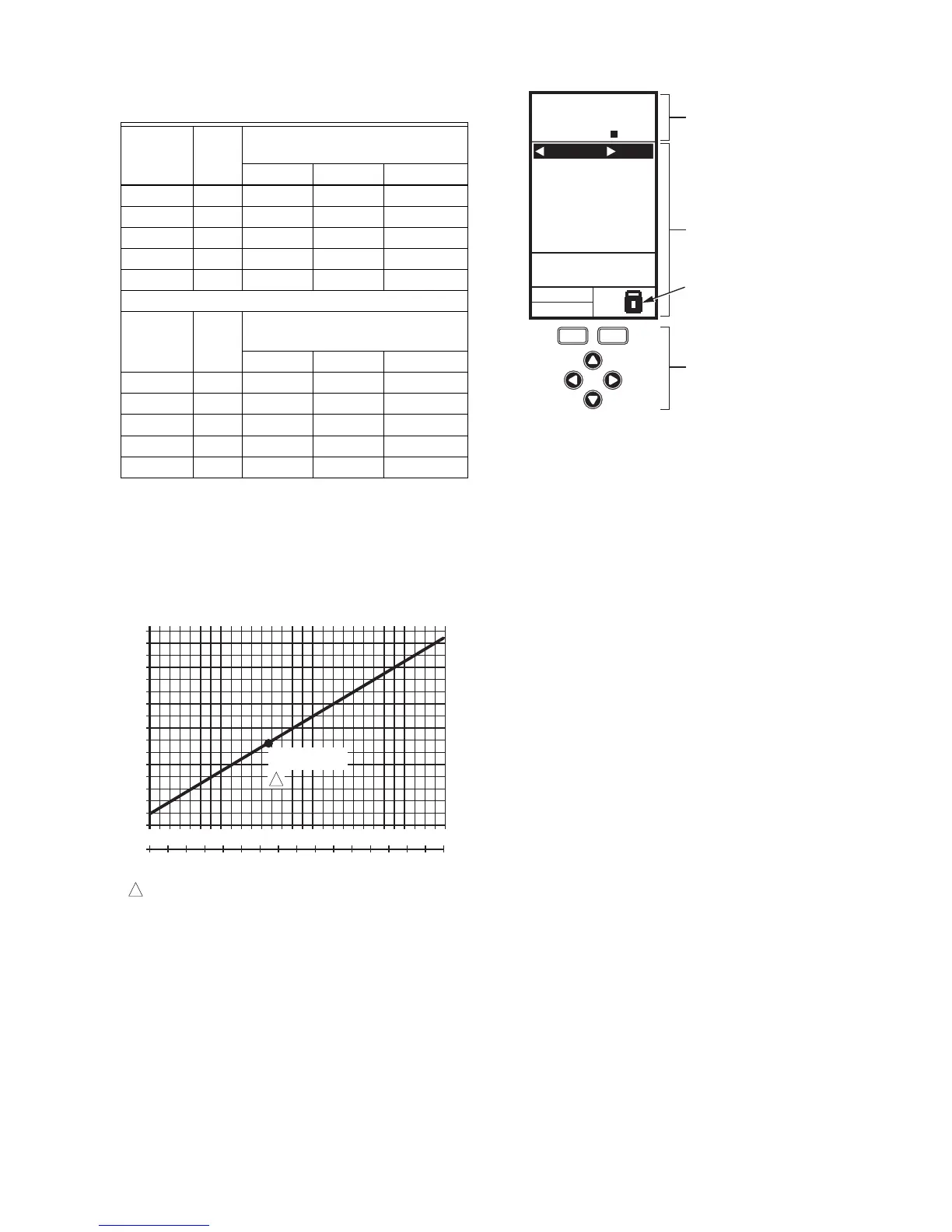
Fig. 19 shows how sensor resistance varies with
temperature for a sensor having a positive temperature
coefficient (PTC) of 2.1 Ohms per degree F (3.85 Ohms
per degree C).
Fig. 19. Sensor Resistance vs. Temperature.
INTERFACE OVERVIEW
The T775U controller uses an LCD panel and 6-button
keypad to provide status information and permit user input
of the programming, setup, and scheduling parameters.
The following figure describes the display areas of the
LCD and the keypad.
Fig. 20. LCD Display - Home Screen And Keypad.
Menu Area – On the home screen, the LCD displays the
configured relays and whether they are active. In
Program, Setup or Schedule mode, the LCD displays the
current menu selection and its order within the menu
hierarchy.
Data Area – On the home screen, the LCD displays the
sensors and outputs status. In Setup or Program mode,
the LCD displays menu choices, parameter selections,
and data values.
Lock Icon – The icon indicates the MENU button is
locked and prevents access to the Setup and Program
menus.
NOTE: Pressing and holding the HOME and MENU but-
tons simultaneously for five seconds locks/
unlocks the MENU button.
6-Button Keypad – The keypad is used to access the
menus and enter values (see “Using the LCD Panel
Interface”).
Using the LCD Panel Interface
The 6-button keypad is used to move through the menus
and enter or change parameter values.
Home Button
Pressing the HOME button at any time exits the current
Programming or Setup display screen and returns to the
home screen as shown in Fig. 20 and Fig. 21.
Menu Button
• Pressing the MENU button always displays the
Program menu. If you are in Setup mode, you exit
setup and return to the Program menu.
• Pressing and holding the MENU button for five
seconds leaves the current screen and displays
the Setup menu.
Left and Right Arrow Buttons (W and X)
Use these buttons to move backward (W) and forward (X)
through the Program and Setup menus.
Table 4. Temperature Sensor Calibration for
Resistance Loss due to Wire Length.
AWG
Rating mΩ/ft
Temperature Offset in
°F (Feet)
a
a
This is the distance from the controller to the sensor
(already accounts for round trip distance).
200 ft 500 ft 1,000 ft
14 2.5 0.46 1.14 2.28
16 4.0 0.72 1.82 3.64
18 6.4 1.16 2.90 5.82
20 10.2 1.86 4.64 9.28
22 16.1 2.92 7.32 14.64
AWG
Rating mΩ/m
Temperature Offset in
°C (Meter)
a
100 m 200 m 300 m
14 8.3 0.44 0.86 1.30
16 13.2 0.68 1.38 2.06
18 21.0 1.10 2.18 3.28
20 33.5 1.74 3.48 5.22
22 52.8 2.74 5.48 8.22
M24304
TEMPERATURE (DEGREES)
RESISTANCE (OHMS)
1403
1317
1231
1145
1059
973
20 40 60 80 100 120 140 160 180 200 220
0 10 20 30 40 50 60 70 80 90 100
°F
°C
0-20-40
120
110
250
-40 -20 -10-30
1489
887
801
1097 ± 0.08 OHMS
AT 77°F (25°C)
POSITIVE TEMPERATURE COEFFICIENT (PTC) OF 2.1 OHMS PER °F
1
1
MOD1 40%
MOD2 60%
DI ON
HOME
RELA
YS 1 2
ON
SENSORS
SENSOR A
78
SENSOR B
84
MENU AREA
home menu
F
o
F
o
DATA AREA
LOCK ICON
6 BUTTON KEYPAD
M24563
 Loading...


