69-1037
2
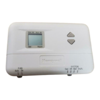
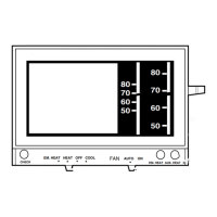
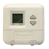
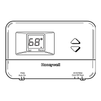
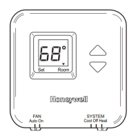
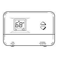
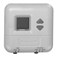
T8411R ELECTRONIC HEAT PUMP THERMOSTAT
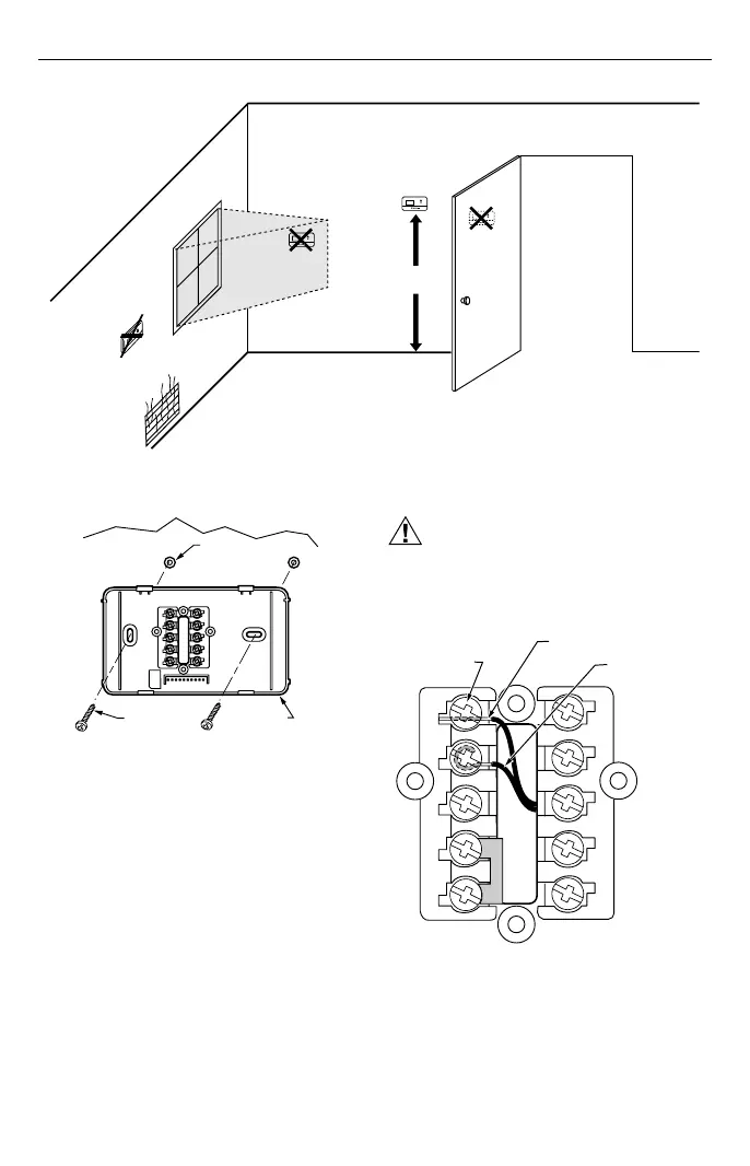
Fig. 1. Typical location of thermostat.
5 FEET
[1.5 METERS]
YES
NO
NO
NO
M11338
Fig. 2. Mounting wallplate to wall.
Wiring
IMPORTANT
Use 18-gauge thermostat cable for proper wiring.
All wiring must comply with local electrical codes and
ordinances.
CAUTION
Disconnect the power supply to prevent electrical
shock or equipment damage.
The shape of the terminals permits insertion of straight or
wraparound wiring connections; either method is acceptable.
See Fig. 3.
Fig. 3. Wiring connections.
M12202
WALL
WALL
ANCHORS (2)
WALLPLATE
MOUNTING
SCREWS (2)
TERMINAL
SCREW
M11334
G
C
R
Y
W1
L
W2
E
B
O
FOR STRAIGHT INSERTION
STRIP 5/16 IN. (8 MM)
FOR WRAPAROUND
STRIP 7/16 IN. (11 MM)
 Loading...