69-1037
4
T8411R ELECTRONIC HEAT PUMP THERMOSTAT
M11332
S
Y
S
T
E
M
Cool O
ff
H
eat Em
. H
t.
Auto On
F
A
N
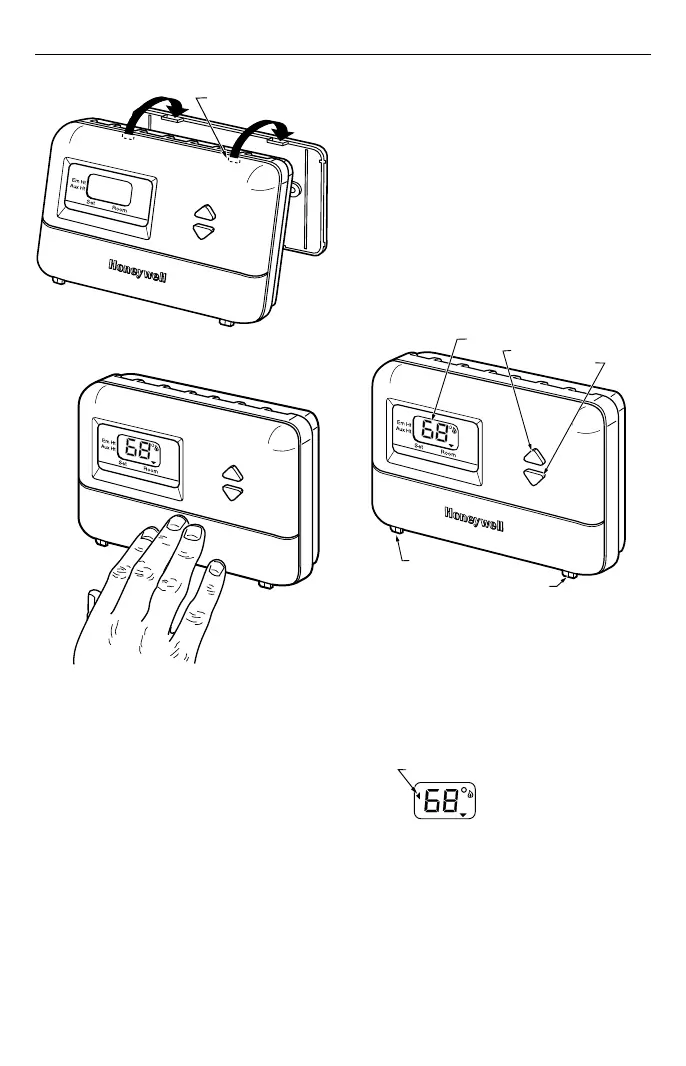
DASHED LINES INDICATE TABS
ON BACK OF THERMOSTAT
S
Y
S
T
E
M
o
l O
ff
H
e
a
t E
m
. H
t.
A
u
to
O
n
F
A
N
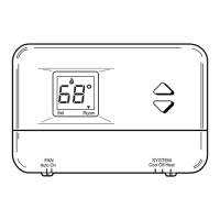
ENGAGE TABS AT TOP OF THERMOSTAT
WITH SLOTS ON MOUNTING PLATE.
PRESS LOWER EDGE OF
CASE TO LATCH.
A
B
Fig. 6. Mounting thermostat to wallplate.
OPERATION
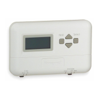
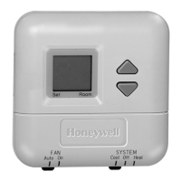
Setting FAN and SYSTEM Switches
Fan and system settings are controlled manually by using
the switches located at the bottom of the thermostat case.
See Fig. 7.
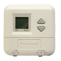
FAN Switch
Fan switch settings are as follows:
On: The fan runs continuously. Use for improved air
circulation.
Auto: Normal setting for most homes. The fan starts
and stops with the equipment.
Slide the switch in the bottom left corner of the thermostat
to select the desired fan setting.
SYSTEM Switch
System switch settings control thermostat operation as
follows:
Cool: Thermostat controls the cooling system.
Off: Both heating and cooling are off.
Heat: Thermostat controls the heating system.
Em Ht: Thermostat cycles Auxiliary Heat (W2) and
Emergency Heat Relay (E) as needed to maintain
setpoint. Terminal L is energized continuously.
(Fault heat relay is on continuously.) Cooling system
is off. Compressor is de-energized.
Slide the switch in the bottom right corner of the thermo-
stat to select the desired system setting.
S
Y
S
T
E
M
C
ool O
ff
H
eat E
m
. H
t.
Auto On
F
A
N
M11330
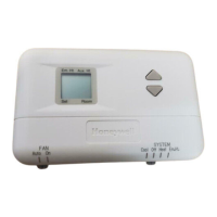
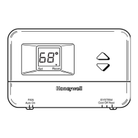
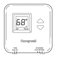
TEMPERATURE DISPLAY
INCREASE SETTING
DECREASE SETTING
FAN SWITCH
SYSTEM SWITCH
Fig. 7. Temperature display and system switches.
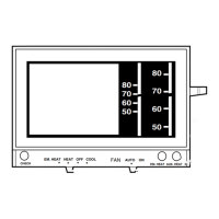
Em Ht and Aux Ht Indications
The indicator points to either Emergency Heat (Em Ht)
or Auxiliary Heat (Aux Ht) when these modes are active.
Em Ht: The indicator points to Em Ht when the
SYSTEM switch is set at Em Ht.
Aux Ht: The indicator points to Aux Ht when auxiliary
backup heat is needed to help handle the heating
load.
Set
Room
M10287
INDICATOR
Em Ht
Aux Ht
Set Temperature Setpoint
NOTE: Temperature setpoint range is 40°F to 99°F
(4°C to 39°C).
 Loading...