T8411R ELECTRONIC HEAT PUMP THERMOSTAT
68-0185—2 4
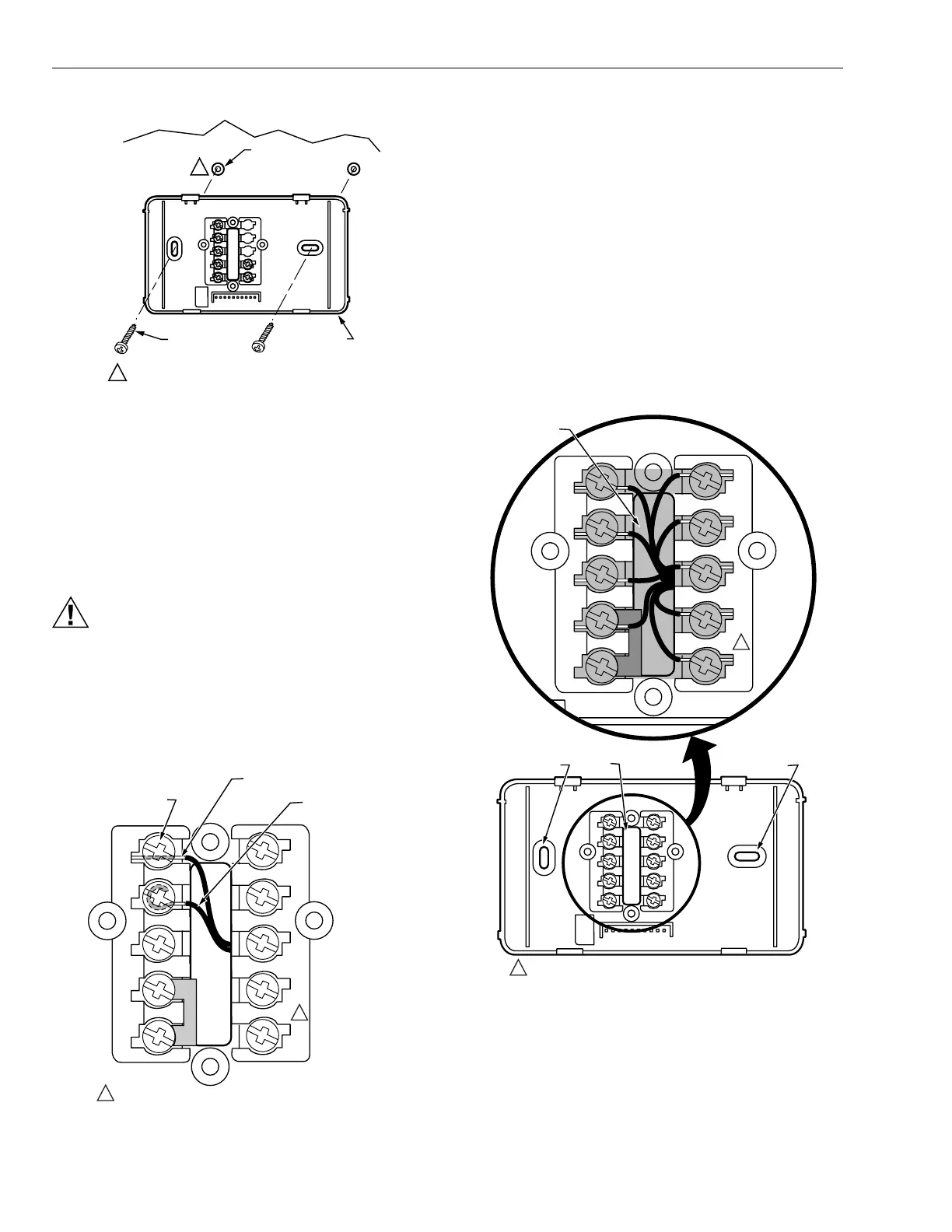
Fig. 3. Mounting wallplate to wall.
Wiring
IMPORTANT
Use 18-gauge thermostat cable for proper wiring.
All wiring must comply with local electrical codes and
ordinances.
CAUTION
Damage to Heating/Cooling System Possible.
Be careful when handling wires during
installation.
Disconnect power at furnace or main breaker/fuse box.
The shape of the terminals permits insertion of straight or
wraparound wiring connections; either method is acceptable.
See Fig. 4.
Fig. 4. Wiring connections.
NOTE: Restrict all wiring to the shaded area between the
terminals. See Fig. 5.
Refer to Fig. 6 for typical wiring hookup. A letter code is
located near each terminal for identification.
1. Loosen the terminal screws on the wallplate and con-
nect the system wires. See Fig. 4.
2. Securely tighten each terminal screw.
3. Push the excess wire back into the hole.
4. Plug the hole with nonflammable insulation to prevent
drafts from affecting the thermostat.
Mounting Thermostat to Wallplate
1. Engage the tabs at the top of the thermostat and wall-
plate.
2. Swing down the thermostat and press the lower edge of
the thermostat onto the wallplate to latch. See Fig. 7.
Fig. 5. Restrict wiring to shaded area.
M12202A
WALL
WALL
ANCHORS (2)
WALLPLATE
WHEN USING WALL ANCHORS, DRILL 3/16 INCH
HOLES FOR DRYWALL, 7/32 INCH HOLES FOR
PLASTER OR WOOD.
MOUNTING
SCREWS (2)
1
1
TERMINAL
SCREW
M11334A
G
C
R
Y
W1
L
W2
E
B
O
FOR STRAIGHT INSERTION
STRIP 5/16 IN. (8 MM)
FOR WRAPAROUND
STRIP 7/16 IN. (11 MM
1
NOT ALL MODELS HAVE BOTH O AND B TERMINALS.
1
KEEP WIRING IN
SHADED AREA
MOUNTING
SCREW HOLE
MOUNTING
SCREW HOLE
WIRING ENTRANCE
HOLE
M11331A
G
C
R
Y
W1
L
W2
E
B
O
1
NOT ALL MODELS HAVE BOTH O AND B TERMINALS.
1
 Loading...