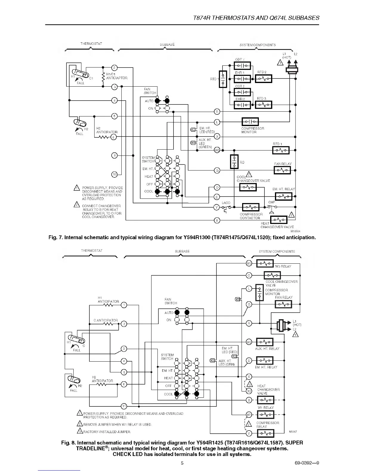
T874R THERMOSTATS AND Q674L SUBBASES
THERMOSTAT
SYSTEM COMPONENTS
L1 L2
(HOT)
Fig. 7. Internal schematic and typical wiring diagram for Y594R1300 (T874R1475/Q674L1520); fixed anticipation.
SUBBASE
THERMOSTA.T SUBBASE SYSTEM COMPONENTS
------
A
----------------
. /
--------------------------------------
A-------------------------------------------- . y
----------------
A
------------
Fig. 8. Internal schematic and typical wiring diagram for Y594R1425 (T874R1616/Q674L1587). SUPER
TRADELINE®; universal model for heat, cool, or first stage heating changeover systems.
CHECK LED has isolated terminals for use in all systems.
5
69-0392—9

 Loading...