T874R THERMOSTATS AND Q674L SUBBASES
SUBBASE
____A
____
SYSTEM COMPONENTS
_________
A_
L1 L2
(HOT)
A "
COMPRESSOR
CONTACTOR
v POWER SUPPLY. PROVIDE DISCONNECT MEANS AND OVERLOAD PROTECTION AS REQUIRED.
IHER M O S IAI
____
A
____
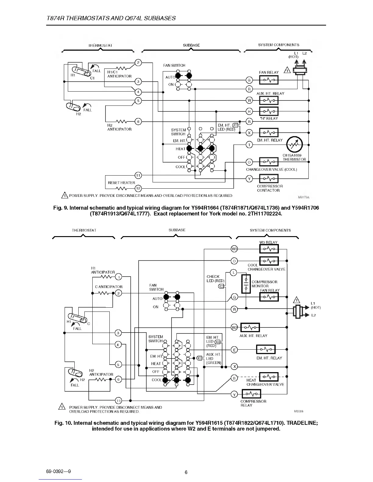
Fig. 9. Internal schematic and typical wiring diagram for Y594R1664 (T874R1871/Q674L1736) and Y594R1706
(T874R1913/Q674L1777). Exact replacement for York model no. 2TH11702224.
THERMOSTAT
SUBBASE
SYSTEM COMPONENTS
r
A
N /
A
N /
A
N
W3 RELAY
L1
(HOT)
L2
Fig. 10. Internal schematic and typical wiring diagram for Y594R1615 (T874R1822/Q674L1710). TRADELINE;
intended for use in applications where W2 and E terminals are not jumpered.
69-0392—9
6

 Loading...