T874R THERMOSTATS AND Q674L SUBBASES
SUBBASE
___
A
____
SYSTEM COMPONENTS
_________
A
_____________
L1 L2
(HOT)
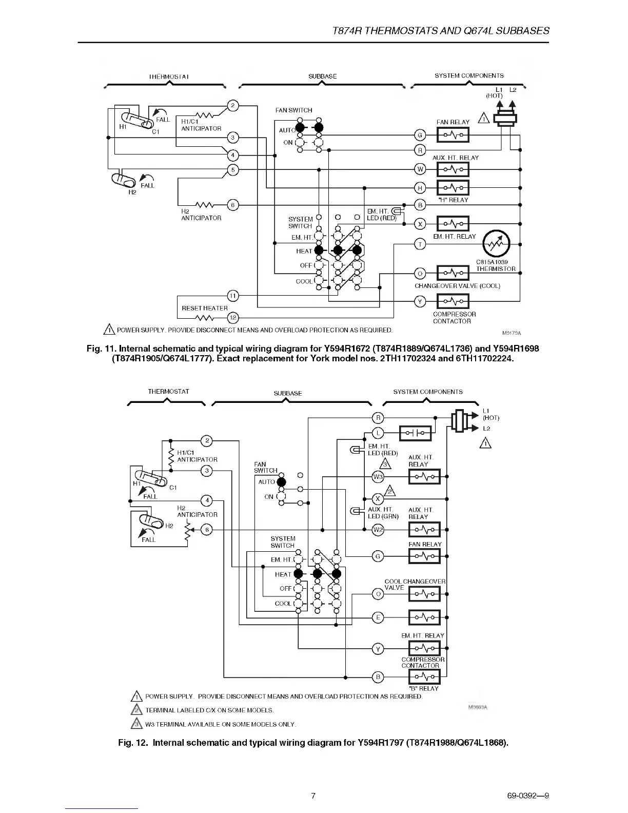
Fig. 11. Internal schematic and typical wiring diagram for Y594R1672 (T874R1889/Q674L1736) and Y594R1698
(T874R1905/Q674L1777). Exact replacement for York model nos. 2TH11702324 and 6TH11702224.
IH ER M OSIAI
____
A
____
/■
THERMOSTAT
____
A
_____
N /
SUBBASE
__
A____
SYSTEM COMPONENTS
\ /
---------------------
/N
--------------------------
^
L1
(HOT)
L2
A
TERMINAL LABELED C/X ON SOME MODELS.
W3 TERMINAL AVAILABLE ON SOME MODELS ONLY.
Fig. 12. Internal schematic and typical wiring diagram for Y594R1797 (T874R1988/Q674L1868).
7
69-0392—9

 Loading...