1 69-0665—1
Application
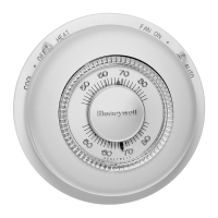
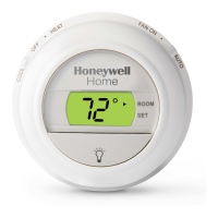
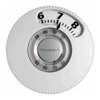
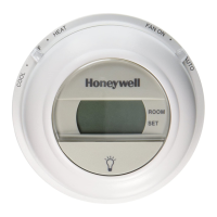
The T87F Universal Thermostat provides temperature
control for 24 to 30 Vac residential heating, cooling or
heating-cooling systems. A 6 in. [152 mm] cover ring and
137421 3-terminal wallplate with Series 20 terminal
markings are included. For heating-only or cooling-only
applications, use the enclosed wallplate. For heating/cool-
ing applications, order a Q539 Subbase, which provides
switching at the thermostat location.
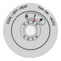
The spdt switch makes one set of contacts on a tempera-
ture fall to operate the heating system. The other set of
contacts make on a temperature rise to operate the cooling
system when the T87F is used to control cooling.
Heat anticipation is adjustable, 0.1 to 1.2A.
Recycling Notice
This control contains mercury in a sealed tube. Do not
place control in the trash at the end of its useful life.
If this control is replacing a control that contains mercury
in a sealed tube, do not place your old control in the trash.
Contact your local waste management authority for
instructions regarding recycling and the proper disposal of
this control, or of an old control containing mercury in a
sealed tube.
If you have questions, call Honeywell Inc. at 1-800-
468-1502.
Installation and Setting
WHEN INSTALLING THIS PRODUCT…
1. Read these instructions carefully. Failure to fol-
low them could damage the product or cause a hazardous
condition.
2. Check the ratings given in the instructions and on
the product to make sure the product is suitable for your
application.
3. Installer must be a trained, experienced service
technician.
4. After installation is complete, check out product
operation as provided in these instructions.
S. M. • Rev. 9-93 • • ©Honeywell Inc. 1993 • Form Number 69-0665—1
T87F
Universal Thermostat
!
M3375
M3375
CAUTION
1. Disconnect power supply to prevent electri-
cal shock or equipment damage.
2. To prevent interference with the thermostat
linkage, keep wire length to a minimum and
run wires as close as possible to the subbase.
3. Do not overtighten thermostat captive mount-
ing screws, because damage to subbase threads
can result.
2. Do not short across coil terminals on relay.
This can burn out thermostat heat anticipator.
IMPORTANT: An incorrectly leveled thermostat will cause
the temperature control to deviate from set point.
LOCATION
Install the thermostat about 5 ft [1.5 m] above the floor
in an area with good air circulation at average temperature.
Do not install the thermostat where it may be affected by:
— drafts or dead spots behind doors and in corners.
— hot or cold air from ducts.
— radiant heat from the sun or appliances.
— concealed pipes and chimneys.
— unheated (uncooled) areas such as an outside wall
behind the thermostat.
This thermostat is a precision instrument and was care-
fully adjusted at the factory. Handle it carefully.
MOUNTING WALLPLATE TO WALL
IMPORTANT:
1. Use plumb line or spirit level to accurately level the
wallplate as in Fig. 1. Inaccurate leveling may cause
thermostat control deviation.
2. When using the T87F with a Q539 Subbase, follow
the mounting and wiring instructions included with
the subbase.
Use cover ring (if desired) and wallplate assembly,
T87F, and mounting screws as shown in Fig. 2.
1. Place cover ring on the wall at the desired location
with the cable entrance holes to the left.
2. Bring the thermostat cable through the bottom en-
trance hole of the cover ring and through the wallplate
entrance hole.
3. Fasten the cover ring and wallplate to the wall with
the mounting screws as shown in Fig. 2.
4. Mount thermostat on a level wallplate to maintain
accurate calibration. See Fig. 1.