2
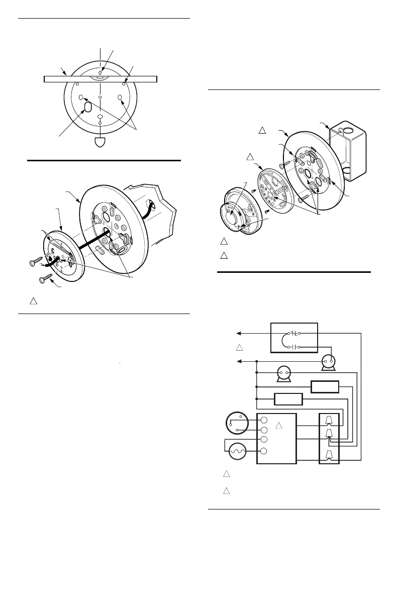
Fig. 1—Leveling wallplate or subbase with
spirit level or plumb line.
SPIRIT
LEVEL
DIAMOND
GUIDES (2)
LEVELING
POSTS (2)
MOUNTING
SLOTS
M3319
VERTICAL
PLUMB LINE
OPENING FOR
THERMOSTAT
WIRING
Fig. 2—Mounting wallplate or subbase to wall.
WALL
1
USE WALLPLATE FOR HEAT APPLICATIONS.
126293 COVER
RING (OPTIONAL)
THERMOSTAT CABLE
ENTERANCE HOLE
NO. 4 X 1 INCH SHEET
METAL SCREWS (2)
WALLPLATE
M3829
MOLDED
LEVELING
POST
MOUNTING WALLPLATE ON OUTLET BOX
Use cover plate, wallplate assembly, T87F, and screws
as shown in Fig. 3.
1. Place the cover plate on the outlet box with the cable
entrance holes toward the bottom.
2. Pull the thermostat cable through the bottom hole.
3. Align the diamonds on the cover ring vertically and
secure cover plate with the screws provided.
NOTE: The side reading “Made in U.S.A.” must be against
the wall.
4. Position the wallplate assembly and pull the thermo-
stat cable through the cable entrance hole.
5. Mount wallplate with the two screws provided.
Tighten screws after the wallplate has been leveled. See
Fig. 1 for leveling instructions.
WIRING
All wiring must comply with local electrical codes and
ordinances. Disconnect power supply before connecting
wiring to prevent electrical shock or equipment damage.
The T87F is adaptable to most 2-wire, 24 to 30 volt
heating systems, and to most 3-wire, 24 to 30 volt
heating systems controlled by a Series 10 Thermostat.
The following hookups are typical applications. See Figs.
4-8. When using the T87F for cooling control, refer to
the hookups in the Q539 Subbase instructions.
For variations of these systems, refer to the installation
instructions for the controlled equipment.
After wiring the wallplate, plug the hole to prevent
drafts that may affect the thermostat.
Fig. 3—Mounting wallplate/subbase to outlet
box.
M3844
OUTLET BOX
COVER
RING
1
CAPTIVE
SCREWS (3)
THERMOSTAT CABLE
ENTRANCE HOLE
T87F
IF OUTLET BOX IS HORIZONTAL, MOUNT COVER RING IN
POSITION SHOWN, BUT FASTEN WITH SCREWS THROUGH "A".
USE WALLPLATE FOR HEAT APPLICATIONS.
1
A
A
Q539
SUBBASE
2
2
Fig. 4—T87F used for 2-wire, spst control of
heating only in a typical oil system. Low
voltage power for the control circuit is supplied
by a transformer in the oil primary control.
R
Y
W
BURNER
MOTOR
FAN
MOTOR
1
POWER SUPPLY. PROVIDE DISCONNECT MEANS AND OVERLOAD
PROTECTION AS REQUIRED.
IGNITION
OIL VALVE
WHITE
ORANGE
BLACK
R8184G
THERMOSTAT
CAD CELL
L1 (HOT)
L2
LIMIT
FAN
COMBINATION FAN
AND LIMIT CONTROL
2
R8184 PROTECTORELAY OIL PRIMARY CONTAINS
INTERNAL TRANSFORMER.
M6105
T
2
1
T
F
F
 Loading...