3 69-0665—1
R
W
1
L1
(HOT)
L2
FAN
MOTOR
COMBINATION
FAN AND LIGHT
CONTROL
LIMIT
FAN
TRANSFORMER
GAS VALVE
T87F
TH
TH TR
TR
M5318
1
POWER SUPPLY. PROVIDE DISCONNECT MEANS AND OVERLOAD
PROTECTION AS REQUIRED.
Y
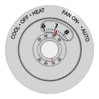
Fig. 5—T87F used for 2-wire, spst control of
heating only in a typical gas system.
1
L1
(HOT)
L2
1
COOLING
CONTACTOR COIL
POWER SUPPLY. PROVIDE DISCONNECT MEANS
AND OVERLOAD PROTECTION AS REQUIRED.
ONLY R AND Y TERMINALS ARE USED FOR
COOLING ONLY.
M3516
R
Y
THERMOSTAT
WALLPLATE OR
SUBBASE
POWER
SUPPLY
2
2
Fig. 8—T87F used in cooling only system.
Fig. 7—T87F used for Series 20, 3-wire, spdt
control of low-voltage motors and electric
radiator valves. Used in applications where
thermostat makes contact on both a rise and
fall in room temperature.
THERMOSTAT
M6102
R
Y
W
LOW LIMIT
OPERATING CONTROL
JUMPER
SERIES 10 OPEN
CIRCUIT HIGH LIMIT
TO THERMOSTAT
CONNECTIONS ON
SERIES 10 VALVE
AT BURNER
B
B
W
W
R
R
Fig. 6—T87F replacing a Series 10 Thermostat
connected to a 3-wire, open-contact, high-limit
control.
MOUNTING THERMOSTAT TO WALLPLATE
To remove standard cover, pull ring outward with fin-
gertips, pressing lightly on dial with thumbs.
Remove and discard the plastic insert protecting the mer-
cury switch.
Align the thermostat over the wallplate and tighten the
three captive mounting screws. These captive screws com-
plete the electrical connections to the thermostat. Adjust
heat anticipator to match current rating of primary control.
See Fig. 9.
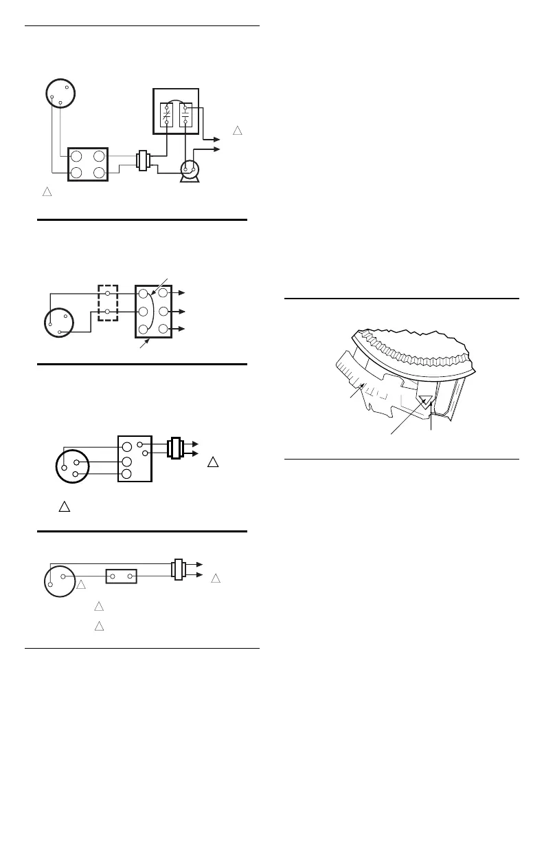
HEAT ANTICIPATOR SETTING
Adjust anticipator to match current rating of primary
control. Rating is usually stamped on the control name-
plate. Move the indicator to the marking that matches this
rating. Indicator may be moved with fingers or pencil point
through hole shown in Fig. 9. If the current rating is not
given, proceed as follows before mounting the thermostat:
1. Connect an ac ammeter of appropriate range (0 to
2.0A, for example) between the R and W terminals on the
wallplate or subbase.
2. Let the system operate for one minute before reading
the ammeter.
3. Move the anticipator indicator to match the amme-
ter reading.
A slightly higher setting to obtain longer burner-on
times (fewer cycles per hour) may be desirable for some
systems.
Fig. 9—Setting heat anticipator current rating.
LONGER
.15
.12
.2
.6
.8
1.0
.5
.4
.3
HOLE SUITABLE FOR
PENCIL POINT
TO MOVE INDICATOR
HEAT
ANTICIPATOR
INDICATOR
SCALE
M1368
EXAMPLE: If burner-on time is too short with a setting of
0.4, adjust to 0.45 and check system operation; adjust
to 0.5 setting and recheck until the desired burner-on
time is obtained.
IMPORTANT: When T87F is used in a Series 20 heat-
ing circuit (requires contact on both a rise and fall
in temperature, see Fig. 7), set anticipator indicator
to 1.2.
TEMPERATURE SELECTION
To select the temperature control point, turn the trans-
parent dial until the desired point on the setting scale (top) is
aligned with the pointer.
RECALIBRATION
The T87F is calibrated at the factory and no recali-
bration should be necessary. If the thermostat is accurately
leveled and still appears to be out of calibration, order
104994A Calibration Wrench. Instructions for recali-
brating are furnished with the wrench.
RED
WHITE
BLUE
137421A
WALLPLATE
W
Y
R
B
W
R
TR
L1
(HOT)
L2
THREE-WIRE SPDT
VALVE OR MOTOR
POWER SUPPLY. PROVIDE DISCONNECT MEANS
AND OVERLOAD PROTECTION AS REQUIRED.
M5319
1
1
 Loading...