69-0882B 2
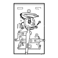
SPIRIT LEVEL
MOUNTING
HOLES (2)
M927
TOP
MOUNTING
HOLES (2)
WIRING
TERMINAL
THERMOSTAT
CABLE OPENING
TO SPRING FINGER
CONTACTS ON THE
THERMOSTAT
(UP TO 12)
POST (2) FOR
MOUNTING
THERMOSTAT
NOTE: The cover is hinged at the top and must be removed
by pulling up at the bottom.
2. Carefully remove and discard the polystyrene packing
insert that protects the mercury switches during shipment.
3. Turn over thermostat base and note the spring fingers
that engage the subbase contacts. Make sure the spring
fingers are not bent flat, preventing proper electrical contact
with the subbase.
4. Note the two tabs on the top inside edge of the
thermostat base. The tabs fit into corresponding slots on top
of the subbase. Mount the thermostat on the subbase.
5. Align the two captive mounting screws in the thermo-
stat base with the posts on the subbase. See Fig. 7. Tighten
both screws. Do not overtighten screws or damage to sub-
base posts can result.
Fig. 4—Barrier configuration.
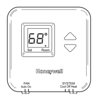
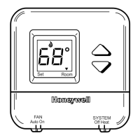
Settings
TEMPERATURE SETTING
Move the heating and cooling setpoint levers to the
desired comfort positions. See Fig. 8. One lever control all
stages of heating, and the other lever controls all stages of
cooling. The minimum differential between the heating and
the cooling setpoint is 3°F (1.7°C), which means the setting
levers are made so they cannot be set closer together than
3°F (1.7°C).
Fig. 3—Subbase components and leveling
procedure.
M925
VERTICAL
OUTLET
BOX
ADAPTER
RING
SUBBASE
COVER
PLATE
MOUNTING
SCREWS (2)
MOUNTING
SCREWS (2)
1
SUBBASE
MOUNTING
SCREWS (2)
HORIZONTAL
OUTLET
BOX
1
2
2
NOT INCLUDED WITH UNIT.
ACCESSORY PARTS AVAILABLE (193121A).
1
2
WIRES THROUGH
WALL OPENING
WALL
WALL
ANCHORS
(2)
SUBBASE
MOUNTING
SCREWS (2)
M926
MOUNTING
HOLES
WIRING THE SUBBASE
All wiring must comply with local electrical codes and
ordinances. Follow equipment manufacturer’s wiring instruc-
tions when available. To wire subbase, proceed as follows:
1. Connect the system wires to the subbase. See Figs. 5
and 6. A letter code is located near each terminal for identi-
fication. The terminal barrier permits straight or conven-
tional wraparound wiring connection. See Fig. 4.
2. Firmly tighten each terminal screw.
3. Fit wires as close as possible to the subbase. Push
excess wire back into the hole.
4. Plug hole with nonflammable insulation to prevent
drafts from affecting the thermostat.
MOUNT THERMOSTAT
1. Remove the thermostat cover by pulling the bottom
edge of the cover upward until it snaps free of the mounting
slots.
FOR STRAIGHT
INSERTION–
STRIP 5/16 in. (8 mm)
FOR WRAPAROUND–
STRIP 7/16 in. (11 mm)
SUBBASE TERMINAL SCREW
M928
BARRIER
Fig. 1—Installation of Q674 Subbase on outlet
box.
Fig. 2—Installation of Q674 Subbase on wall.
 Loading...