V4043, V4044 VALVES; V8043, V8044 ZONE VALVES
3 95-6983—11
3. IMPORTANT: Take care not to burn the plastic por-
tion of the composite adapter plate when soldering.
4. Sweat the joints, keeping the outer surface free
from solder. DO NOT use silver solder because of
the high melting temperature required.
To Install Replacement Powerhead
SYSTEMS WITH OLD STYLE VALVE BODIES (SERIES
1-5)
To install a replacement powerhead in a system with an
old style body (series 1-5), the valve body must be
converted to accept the new powerhead using Part No.
40003918 Conversion Kit. The kit includes a metal plate
with a driveshaft and rubber plug, O-ring, and four screws.
IMPORTANT
Converting the valve body for use with the new
powerhead does not require removal of the valve
body from the pipeline. However, it is necessary
to drain the water from the system before begin-
ning the conversion.
1. Disconnect the power supply before connecting the
wiring to prevent electrical shock or equipment
damage.
2. Disconnect the leadwires to the powerhead at the
terminal block or conduit connection. Remove the
conduit or cable connector if fitted. Label each wire
for rewiring later.
3. Drain the water from the system.
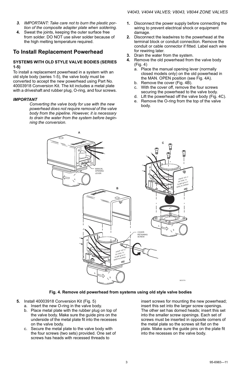
4. Remove the old powerhead from the valve body
(Fig. 4)
a. Place the manual opening lever (normally
closed models only) on the old powerhead in
the MAN. OPEN position (see Fig. 4A).
b. Remove the cover (Fig. 4B).
c. With the cover off, remove the four screws
securing the powerhead to the valve body.
d. Lift the powerhead off the valve body (Fig. 4C).
e. Remove the O-ring from the top of the valve
body.
Fig. 4. Remove old powerhead from systems using old style valve bodies
5. Install 40003918 Conversion Kit (Fig. 5)
a. Insert the new O-ring in the valve body.
b. Place metal plate with the rubber plug on top of
the valve body. Make sure the guide pins on the
underside of the metal plate fit into the recesses
on the valve body.
c. Secure the metal plate to the valve body with
the four screws (two sets) provided. One set of
screws has heads with recessed threads to
insert screws for mounting the new powerhead;
insert this set into the larger screw openings.
The other set has domed heads; insert this set
into the smaller screw openings. Each set of
screws must be inserted in opposite corners of
the metal plate so the screws sit flat on the
plate. Make sure the guide pins on the plate fit
into the recesses on the valve body.
A
AUTO
MAN
OPEN
MANUAL
OPENING
LEVER
COVER
RETAINING
SCREW
M10174
A
B
V8043F 1051
24V 50/60 CY
.32 AMP @ 60 CY
MADE IN CANADA
6
A
B
V8043F 1051
24V 50/60 CY
.32 AMP @ 60 CY
MADE IN CANADA
6
A
B
C
 Loading...