69-0329—44
24V
24V (GND)
587 CONTROL MODULE
ALARM
VALVE
VALVE
GND
TEMPERATURE
CONTROLLER
POWER SUPPLY. PROVIDE DISCONNECT MEANS AND OVERLOAD
PROTECTION AS REQUIRED.
ALTERNATE LIMIT CONTROLLER LOCATION.
MAXIMUM IGNITER-SENSOR CABLE LENGTH: 3 ft. [.9 m] OR LESS.
3 A REPLACEABLE FUSE.
ALARM TERMINAL PROVIDED ON SOME MODELS.
M9043
MV
MV
L1
(HOT)
L2
1
2
1
2
3
DUAL VALVE
COMBINATION
GAS CONTROL
Q347 IGNITER-SENSOR
BURNER
4
4
5
IGNITER-SENSOR AND
BURNER GROUND
3
5
ALARM, IF USED
Fig. 6—Wiring connections for 24 volt con-
trol in S87 direct ignition system.
WIRING
Follow the wiring instructions furnished by the appli-
ance manufacturer, if available, or use the general instruc-
tions provided below. Where these instructions differ from
the appliance manufacturer, follow the appliance
manufacturer’s instructions.
All wiring must comply with applicable electrical codes
and ordinances.
Disconnect power supply before making wiring connec-
tions to prevent electrical shock or equipment damage.
1. Check the power supply rating on the gas control and
make sure it matches the available supply. Install the trans-
former, thermostat, and other controls as required.
2. Connect control circuit to gas control terminals. See
Figs. 4, 6, and 7.
3. Adjust thermostat heat anticipator to 0.50A rating
stamped on valve operator.
Fig. 7—Wiring connections for 24 volt control
in S89 direct ignition system.
WHITE
BLUE
BLACK
BLUE
HOT
SURFACE
IGNITER-
SENSOR
VALVE
VALVE (GND)
24V
TH-W
24V (GND)
GND (BURNER)
S89C,G,J/S890C,G,J
HOT SURFACE
IGNITION CONTROL
L2
HSI
L1
HSI
LIMIT
CONTROLLER
BURNER
GROUND
THERMOSTAT
OR CONTROLLER
DUAL VALVE
COMBINATION
GAS CONTROL
POWER SUPPLY. PROVIDE DISCONNECT MEANS AND OVERLOAD
PROTECTION AS REQUIRED. MAKE SURE L1 AND L2 ARE NOT
REVERSED; THIS WOULD PREVENT FLAME DETECTION.
ALTERNATE LIMIT CONTROLLER LOCATION.
SEN TERMINAL AND Q354 FLAME SENSOR ON D MODELS ONLY.
M9047
MV
MV
L1
(HOT)
L2
VENT
DAMPER PLUG
1
2
1
2
3
3
SEN
Q354 FLAME
SENSOR
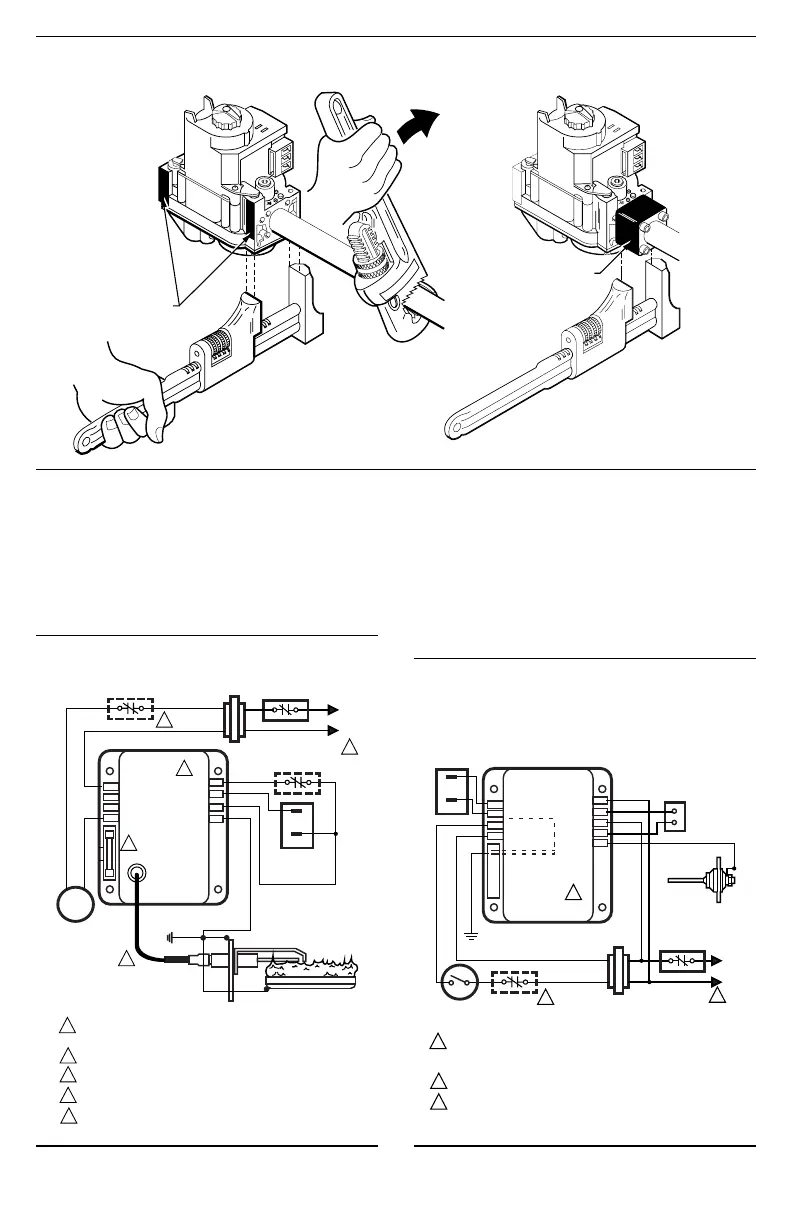
APPLY WRENCH
FROM TOP OR
BOTTOM OF GAS
CONTROL TO
EITHER SHADED AREA
WHEN FLANGE IS NOT USED
APPLY WRENCH
TO FLANGE ONLY
WHEN FLANGE IS USED
M3084A
Fig. 5—Proper use of wrench on gas control with and without flanges.
 Loading...


