EasyManua.ls Logo

Honeywell V4043A User Manual

Honeywell V4043A
20 pages
To Next Page IconTo Next Page
Page #1 background imageLoading...
Page #1 background image
PRODUCT DATA
Put UPC Code Here
60-2133-10
V4043A,B,E,J; V4044A,B;
V8043A,B,E,F,J; V8044A,B,E
Motorized Valves
APPLICATION
These valves consist of an actuator motor and valve assembly
for controlling the flow of hot or cold water, or steam.
IMPORTANT
These valves are not for use in systems containing
dissolved oxygen.
FEATURES
The V4043 and V8043 provide 2-position, straight-
through control of water.
The V4044 and V8044 provide 2-position diverting
control of water.
Compact construction for easy installation.
Manual opener for valve operation on power failure.
Valve returns to automatic position when power is
restored.
Choice of sweat or flare fitting brass end connections
for standard copper tubing.
Motor can be replaced by removing one screw, without
disturbing the valve body or draining the system.
Complete powerhead may be removed or replaced
without breaking the line connections or draining the
system.
All models can be installed without disassembling the
valve.
Fits under the cover of most baseboards.
Available with integral auxiliary end switch (V4044B;
V8043E,F; V8044E) to permit sequencing of auxiliary
equipment.
V4043E and V8043J provide straight-through control of
steam.
Contents
Application.........................................................................1
Features ............................................................................1
Specifications ....................................................................2
Ordering Information .........................................................2
Installation .........................................................................8
Operation and Checkout ...................................................19
Question and Answer IconNeed help?

Do you have a question about the Honeywell V4043A and is the answer not in the manual?

Honeywell V4043A Specifications

General IconGeneral
Voltage24V AC
ApplicationHeating systems
Maximum Operating Pressure10 bar
Body MaterialBrass
Seat MaterialEPDM
Operating Temperature0 to 90 °C
Pipe Size15mm, 22mm
Actuator TypeMotorized
Valve Size15mm, 22mm
Maximum Operating Temperature120°C
Ambient Temperature Range0°C to 40°C

Summary

APPLICATION

FEATURES

SPECIFICATIONS

TRADELINE® Models

Details specifications for TRADELINE® models, a packaged selection for stocking ease.

Standard Models

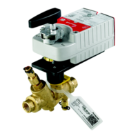
Describes the different standard models of motorized valves and their basic functions.

Flow and Temperature Ratings

Provides critical data on flow capacity (Cv, kv) and temperature limits for various valve models.

ORDERING INFORMATION

How to Find Maximum Valve Operating Temperature

How to Find Valve Pressure Drop

INSTALLATION

MOUNTING

Instructions on proper valve mounting positions and orientation for optimal performance.

Powerhead Replacement

Detailed procedure for replacing the powerhead on old and new style valve bodies.

WIRING

Typical Valve Wiring Diagrams

Illustrates common wiring configurations for individual motorized valves.

Zone System Wiring

Diagrams for wiring zone systems, including multi-zone setups with transformers.

Wiring to Other Systems

Guidance on wiring valves to existing systems like Taco, Dole, Flair, and White-Rodgers.

OPERATION AND CHECKOUT

Operation

Explains automatic and manual operation modes, including normally closed/open behavior.

Checkout

Steps to verify correct valve operation after installation, checking opening and closing.

Service

Guidance for trained technicians on valve maintenance, troubleshooting, and common issues.