V4043A,B,E,J; V4044A,B; V8043A,B,E,F,J; V8044A,B,E MOTORIZED VALVES
19 60-2133—10
OPERATION AND CHECKOUT
On 24 V systems, never jumper the valve coil
terminals even temporarily. This may burn out the
heat anticipator in the thermostat.
Operation
AUTOMATIC OPERATION
On a call for heat by the zone thermostat, the valve opens and
its auxiliary switch contacts make, closing the circuit to the
system circulator. In a multizone system with all the valve
auxiliary switches wired in parallel, any zone calling for heat
can operate the circulator. When the call for heat ends, the
valve closes by integral spring return. The auxiliary switch
contacts break the circulator circuit.
MANUAL OPERATION
The motorized valve can be opened manually by lifting the
manual opening lever over the stop and pushing slowly and
firmly to the MAN. OPEN position. The stop permits the valve
to be locked in the open position. The valve returns to
automatic position when the valve is energized.
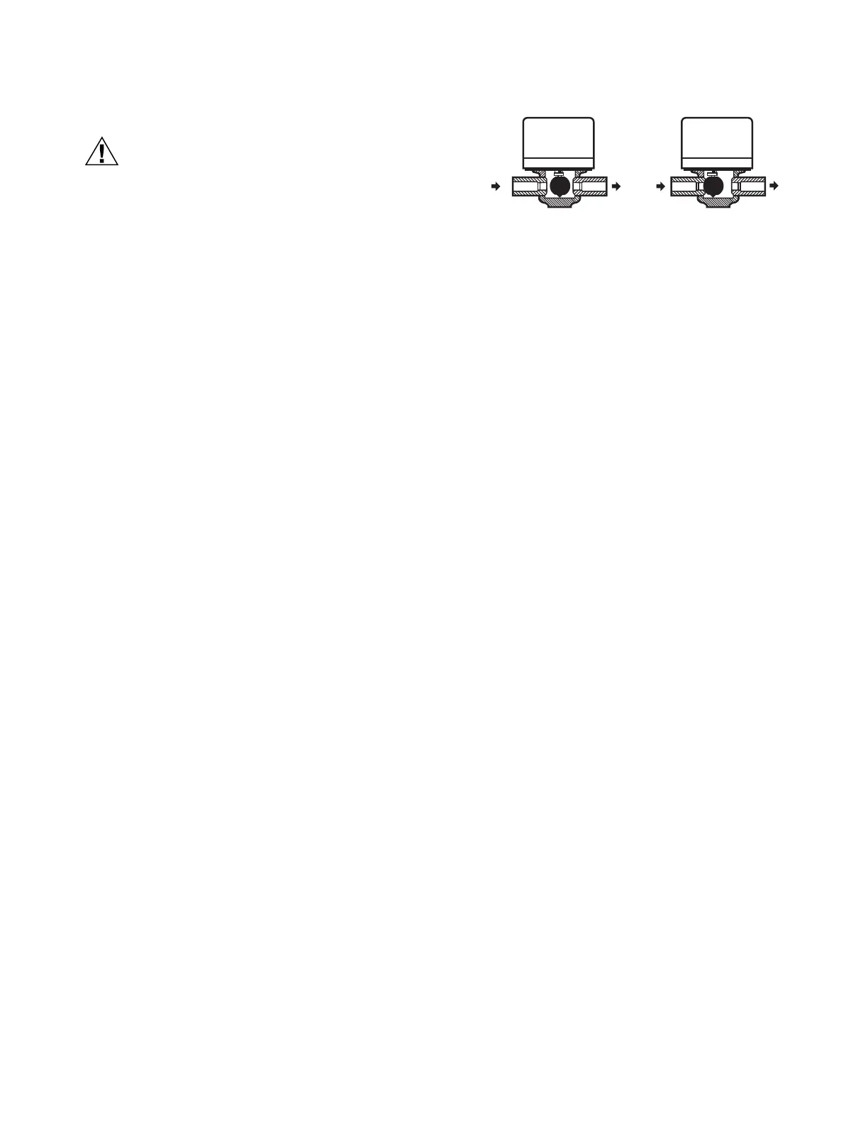
NORMALLY CLOSED MODELS
With the manual opener set to AUTO and the powerhead
energized, the valve is opened as shown in Fig. 36A. When the
powerhead is de-energized, a spring-return mechanism drives
the valve to the closed position as shown in Fig. 36B. The
valve can also be opened with no electrical power by moving
the manual opening lever over the stop and pushing slowly and
firmly to the MAN. OPEN position. The stop permits the valve
to be locked in the open position. The valve returns to the
automatic position when the valve is energized.
Auxiliary switch is not energized when the valve is manually
opened.
NORMALLY OPEN MODELS
When the powerhead is de-energized, a spring-return
mechanism drives the valve to the open position (Fig. 36A).
When energized, the valve is closed as shown in Fig. 36B. A
reverse-acting thermostat is required to control a normally
open valve.
NOTE: Inlet Port is stamped “A”, Outlet Port is stamped “B”
on the valve body.
Fig. 36. V8043 operation for normally closed valve.
Checkout
1. Raise the setpoint on the zone thermostat above the
room temperature to initiate a call for heat.
2. Observe all control devices-the valve should open and
the auxiliary switch should make the circuit to the circula-
tor or other valve at the end of the opening stroke.
3. Lower the setpoint on the zone thermostat below the
room temperature.
4. Observe the control devices. The valve should close and
the auxiliary equipment should stop.
Service
This valve should be serviced by a trained, experienced
service technician.
1. If the valve is leaking, drain the system and check to see
if the O-ring needs replacing.
2. If the gear train is damaged, replace the entire power-
head assembly. See the Installation section. If the motor
is burned out, replace the motor. See Replacement Parts
list in the TRADELINE® Catalog.
NOTE: Honeywell zone valves are designed and tested for
silent operation in properly designed and installed
systems; however, water noises can occur as a result
of excessive water velocity or piping noises can occur
in high temperature (higher than 212° F [100° C]) sys-
tems with insufficient water pressure. Valves are
designed for normal cycling operations. Product life
will be shortened if energized continuously.
NOTE: These hydronic valves are not suitable for use in open
loop systems where there is air exposure.
B
OUT
OPEN POSITION
A
A
IN
B
OUT
CLOSED POSITION
B
A
IN
M5951

 Loading...


