EasyManua.ls Logo

Honeywell VR8215 Series - User Manual

Honeywell VR8215 Series
8 pages
Print Icon
To Next Page IconTo Next Page
Loading...
INSTALLATION INSTRUCTIONS
69-2253-01
VR8215S,T
Direct Ignition Combination
Gas Controls
APPLICATION
The VR8215S,T Direct Ignition Combination Gas
Controls are used in gas-fired appliances with up to 150
ft
3
/hr capacity at 1 in. wc pressure drop on natural gas.
They have been optimized for direct ignition applications
and include a switch and a pressure regulator.
Valve capacities are shown in Table 1.
Table 2 provides gas capacity conversion factors.
For suffix letter designation, see Table 3 or 4.
Table 1. Valve Capacity.
a
a
Capacity based on 1000 Btu/ft
3
, 0.64 sp gr natural gas at 1 in. wc pressure drop.
b
Minimum regulation for LP gas is 30,000 Btuh.
Table 2. Gas Capacity Conversion Factor.
Table 3. Model Number Suffix Letter Designation.
SPECIFICATIONS
Body Pattern: Straight through; see Table 1 for inlet
and outlet size.
Electrical Ratings:
Voltage and Frequency: 24 Vac, 60 Hz.
Current Draw: 0.5A.
Capacity: See Table 1.
Conversion:
Use conversion factors in Table 2 to convert capacities
for other gases.
Regulation Range: See Table 1.
Natural-LP Gas Conversion Kits: See Table 4.
Approvals:
CSA Design Certificate.
Table 4. Natural-LP Gas Conversion Kits.
Model
Size Inlet-
Outlet (in.)
AGA Certified
Capacity for Natural
Gas
AGA Certified Minimum
Regulation for
Natural Gas
AGA Certified Maximum
Regulation for
Natural Gas
ft
3
/hr ft
3
/hr ft
3
/hr
VR8215 1/2 x 1/2 150
15
b
200
Gas Specific Gravity
Multiply Listed
Capacity By
Manufactured 0.60 0.516
Mixed 0.70 0.765
Propane 1.53 1.62
Model Number
Suffix Letter
Ambient
Temperature
Range
Pressure
Regulator Type
S -40°F to 175°F
(-40°C to +79°C)
Standard
T Slow Opening
Model Number Suffix Letter Kit to Convert Natural Gas to LP Kit to Convert LP to Natural Gas
S, T 396221 396222
Question and Answer IconNeed help?

Do you have a question about the Honeywell VR8215 Series and is the answer not in the manual?

Summary

PLANNING THE INSTALLATION

WARNING: Fire or Explosion Hazard

Safety warnings about property damage, severe injury, or death.

Frequent Cycling

Control wear due to high cycling rates; requires monthly checkout.

Water or Steam Cleaning

Protect control from water/steam during cleaning procedures.

High Humidity or Dripping Water

Protect control from moisture, ensure air circulation to prevent condensation.

Corrosive Chemicals

Protect control from chemical exposure that causes failure.

Dust or Grease Accumulation

Provide covers to limit contamination from dust/grease.

Heat

Protect control from excessive temperatures by ensuring ambient temp is within rating.

INSTALLATION

WARNING: Fire or Explosion Hazard

Safety warnings about property damage, severe injury, or death during installation.

Converting Gas Control from Natural Gas to LP Gas (or LP Gas to Natural Gas)

WARNING: Fire Or Explosion Hazard

Safety warnings related to gas conversion hazards.

Installation Procedures

Install Bushings To Control

Steps for installing bushings onto the gas control inlet/outlet.

Location

Guidance on optimal placement of the gas control within the appliance.

Install Piping to Control

Instructions for connecting gas piping or tubing to the control.

Install Control

Steps for mounting and connecting the gas control itself.

Wiring

WARNING: Electrical Shock Hazard or Equipment Damage Hazard.

Safety warnings about injury, death, or equipment damage from electrical issues.

STARTUP AND CHECKOUT

On-Off Switch

Operation of the on-off switch for controlling main gas flow.

Perform Gas Leak Test

Procedure to detect gas leaks after installation or service.

Turn On System

Steps to put the system into an operational state.

Turn On Main Burner

Instructions for activating the main burner.

Check and Adjust Gas Input and Burner Ignition

Standard and Slow-Opening (S and T) Models

Procedures for checking and adjusting gas input and burner ignition for specific models.

Check Safety Lockout (Slow-Opening Controls Only)

WARNING: Fire or Explosion Hazard

Safety warnings for performing the safety shutdown test.

MAINTENANCE

WARNING: Fire or Explosion Hazard

Safety warnings against disassembling or repairing the gas control.

CAUTION: Equipment Damage Hazard

Warning against shorting valve coil terminals, which can damage components.

SERVICE

WARNING: Fire or Explosion Hazard

Safety warnings regarding disassembly, repair, or cleaning of the control.

If Main Burner Does Not Come On With Call For Heat

Troubleshooting steps for when the main burner fails to ignite.

INSTRUCTIONS TO THE HOMEOWNER

WARNING: Fire or Explosion Hazard

Safety warnings for homeowners, including gas leak procedures.

To Turn ON Appliance

STOP! Read the Warnings Above Before Proceeding.

Mandatory safety instructions before operating the appliance.

Turning Off the Appliance

Vacation Shutdown

Procedure for setting the thermostat for vacation shutdown.

Complete Shutdown

Steps to completely turn off power and gas supply to the appliance.

Overview

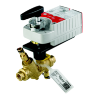
The Honeywell VR8215S,T is a Direct Ignition Combination Gas Control designed for use in gas-fired appliances. It integrates a switch and a pressure regulator, optimized for direct ignition systems.

Function Description:

The VR8215S,T controls the flow of gas to the main burner in gas-fired appliances. It is specifically designed for direct ignition applications, where an igniter directly lights the main burner without a standing pilot. The control includes a pressure regulator to maintain a consistent gas pressure to the burner and an on-off switch for manual gas flow control. It is suitable for both natural gas and LP gas applications, with conversion kits available for switching between gas types. The control is designed to operate in conjunction with a direct ignition module (e.g., S87B, S89C,G,J/S890C,G,J Hot Surface Ignition Control) and a thermostat or controller.

Important Technical Specifications:

  • Capacity: Up to 150 ft³/hr (natural gas) at 1 in. wc pressure drop.
  • Body Pattern: Straight through.
  • Inlet/Outlet Size: 1/2 x 1/2 inches.
  • Electrical Ratings:
    • Voltage and Frequency: 24 Vac, 60 Hz.
    • Current Draw: 0.5A.
  • Regulation Range:
    • AGA Certified Minimum Regulation for Natural Gas: 15 ft³/hr.
    • AGA Certified Maximum Regulation for Natural Gas: 200 ft³/hr.
    • Minimum regulation for LP gas is 30,000 Btuh.
  • Pressure Regulator Specification (in. wc):
    • Natural Gas (Standard/Slow):
      • Nominal Inlet Pressure Range: 5.0-7.0
      • Factory Set Nominal Outlet Pressure: 3.5
      • Setting Range: 2.5-3.5
    • LP Gas (Standard/Slow):
      • Nominal Inlet Pressure Range: 12.0-14.0
      • Factory Set Nominal Outlet Pressure: 10.0
      • Setting Range: 8.0-12.0
  • Ambient Temperature Range (Suffix S, T): -40°F to 175°F (-40°C to +79°C).
  • Pressure Regulator Type:
    • Suffix S: Standard
    • Suffix T: Slow Opening
  • Approvals: CSA Design Certificate.
  • Natural-LP Gas Conversion Kits:
    • Natural Gas to LP: Kit 396221
    • LP to Natural Gas: Kit 396222

Usage Features:

  • Installation Flexibility: Can be mounted in any direction, but gas flow must be in the direction of the arrow on the bottom of the control.
  • Gas Type Conversion: Controls with standard and slow-opening regulators (suffix S or T) can be converted between natural gas and LP gas using specific conversion kits. This requires changing the main orifices and following appliance manufacturer specifications.
  • On-Off Switch: The electronic on-off switch is typically shipped in the ON position. It prevents main gas flow when OFF and permits flow (under thermostat/module control) when ON.
  • Sediment Trap: Installation of a sediment trap in the gas supply line is required to prevent contamination of the gas control.
  • Pipe Connections: Use new, properly reamed pipe or tubing. Apply pipe compound only to the pipe, leaving two end threads bare. Do not use Teflon tape.
  • Pressure Adjustment: The pressure regulator can be adjusted using a screwdriver after removing the adjustment cap screw.
  • Safety Lockout Check: For slow-opening controls (VR8215T), a safety lockout time check is required to ensure proper system function, ensuring the ignition control safety lockout time exceeds 8.5 seconds.
  • Safety Shutdown Performance: Regular testing of the safety shutdown performance is crucial, involving turning off the gas supply and observing the ignition sequence and module lockout.
  • Homeowner Instructions: Provides clear steps for turning the appliance ON and OFF, including warnings about gas leaks and physical damage to the control.

Maintenance Features:

  • Preventive Maintenance: Regular preventive maintenance is crucial, especially in commercial cooking, agricultural, and industrial applications due to high cycling rates (100,000 to 200,000 cycles per year) and exposure to harsh environments.
  • Maintenance Frequency: Determined by application-specific factors such as cycling frequency (monthly for high-cycle appliances), intermittent use (before and after seasonal use), consequence of unexpected shutdown (more often for critical systems), and environmental conditions (more often for dusty, wet, or corrosive environments).
  • Checkout Procedure: The maintenance program should include regular checkout of the control as outlined in the Startup and Checkout section, and the control system as described in the appliance manufacturer literature.
  • Replacement Criteria: The system should be replaced if it does not perform properly, has operated for more than 200,000 cycles, or shows signs of being wet.
  • No User-Serviceable Parts: The gas control contains no replaceable components. Disassembly, repair, or cleaning by unauthorized personnel can damage the control and lead to gas leakage.
  • Troubleshooting: If the main burner does not come on with a call for heat, check the on-off switch position, thermostat setting, and voltage across the quick connect terminals. Replace the gas control if proper voltage is present but the burner does not ignite.
  • Environmental Protection: To prevent malfunction and damage, the control should be protected from steam cleaning, high humidity, dripping water, corrosive chemicals, dust, grease accumulation, and excessive heat. Proper insulation, shielding, and air circulation are recommended in high-temperature environments. Covers should be used in dusty or greasy environments.

Honeywell VR8215 Series Specifications

General IconGeneral
BrandHoneywell
ModelVR8215 Series
CategoryControl Unit
LanguageEnglish

Related product manuals