1 68-0047—2
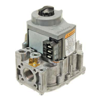
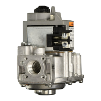
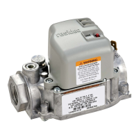
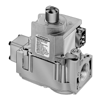
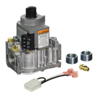
VR8204; VR4204
Intermittent Pilot Dual Automatic
Valve Combination Gas Controls
The VR8204 AND VR4204 Intermittent Pilot
Dual Automatic Valve Combination Gas Controls
are used in gas-fired, intermittent pilot appli-
ances. The controls include a safety shutoff, a
manual valve, two automatic operators, a pres-
sure regulator, a pilot adjustment screw and a
conduit cover (VR4204 only).
■ VR8204 used with S8600, S8610 and S8620 Control
Modules.
■ VR4204 used with 120 Vac intermittent ignition mod-
ules.
■ VR8204 for use with 24 Vac heating appliances and
VR4204 for use with 120 Vac heating appliances that
burn natural or manufactured gas, or liquified petroleum
(LP) gas.
■ Capacity rated at 150 cfh at 1 in. wc pressure drop
[4.2 m
3
/hr at 0.25 kPa].
■ Solenoid-operated first automatic valve opens on ther-
mostat call for heat and closes when call for heat ends.
■ Diaphragm-operated second automatic valve opens un-
der control of the regulator and closes if gas or power
supply is interrupted.
■ Two-position gas control knob has ON and OFF posi-
tions.
■ All adjustments and wiring connections are accessible
from top of the control.
■ Compact size.
■ Straight-through body pattern; right angle adapters avail-
able for inlet and outlet.
■ 1/2 in. inlet and 1/2 in. outlet; adapters available for 3/8
or 3/4 in.
■ Adjustable servo regulator effectively maintains almost
constant gas output pressure under wide fluctuations in
gas supply pressure.
■ Inlet and outlet screens included.
■ Pilot filter included.
■ Wiring terminal block color-coded orange to indicate
intermittent pilot control.
■ May be installed at any angle between 0 and 90 degrees
from the upright position, including vertically.
■ 1/4 in. male quick-connect terminals for electrical con-
nections.
■ 0° F to 175 F° [-18° C to +79° C] temperature range
standard; -40° F to 175° F [-40° C to +79° C] available.
■ lnlet and outlet pressure taps provided; both taps acces-
sible from top of control.
■ Standard-, slow- and step-opening models available.
CONTENTS
Specifications ............................................... 2
Ordering Information .................................. 2
Installation ................................................... 4
Startup and Checkout .................................. 8
Maintenance .............................................. 10
Operation ................................................... 10
Service ........................................................ 13
G. S. • Rev. 1-94 • ©Honeywell Inc. 1994 • Form Number 68-0047—2




 Loading...