7 68-0047—2
VR8204; VR4204
INSTALLATION
5. Connect other end of tubing to pilot burner according
to pilot burner manufacturer instructions.
WIRING
Follow the wiring instructions furnished by the appli-
ance manufacturer, if available, or use the general instruc-
tions provided below. Where these instructions differ from
the appliance manufacturer, follow the appliance manufac-
turer instructions.
All wiring must comply with applicable electrical codes
and ordinances.
Disconnect power supply before making wiring connec-
tions to prevent electrical shock or equipment damage.
1. Check the power supply rating on the gas control and
make sure it matches the available supply. Install thermo-
stat and other controls as required.
2. For VR4204, when the gas control is installed exter-
nal to the appliance, install the conduit cover on the conduit
fitting. Do not secure conduit cover at this time.
3. Connect control circuit to gas control terminals. See
Figs. 5, 8 and 9.
NOTE: Use leadwires with insulated terminals.
4. For VR4204, make sure the conduit cover is in
position and secured to the gas valve with the screw pro-
vided. See Fig. 2.
5. Adjust thermostat heat anticipator as instructed in the
appliance manual (i.e., usually 0.1A for VR4204; 0.5A for
VR8204).
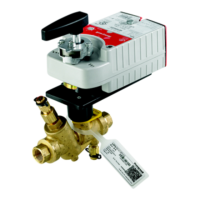
Fig. 8—Wiring connections for 24 volt control
in intermittent ignition system with S8600.
MV MV/PV PV
GND
(BURNER)
24V
GND
24V
SPARK
S8600
POWER SUPPLY. PROVIDE DISCONNECT MEANS
AND OVERLOAD PROTECTION AS REQUIRED.
ALTERNATE LIMIT CONTROLLER LOCATION.
MAXIMUM WIRE LENGTH 3 ft [.9 m].
CONTROLS IN 24V CIRCUIT MUST NOT BE IN
GROUND LEG TO TRANSFORMER.
FOR MODULE WITH TH-W TERMINAL AND VENT DAMPER
PLUG, CONNECT THERMOSTAT TO TH-W. LEAVE
24V OPEN. DO NOT REMOVE VENT DAMPER PLUG.
1
2
3
4
5
M9056
GROUND
PILOT GAS
SUPPLY
2
4
3
Q345, Q346,
Q348, Q362, Q381
PILOT BURNER/
IGNITER-SENSOR
L1
(HOT)
1
L2
LIMIT
CONTROLLER
THERMOSTAT
5
TH-W
(OPT)
VENT
DAMPER
PLUG
(OPT)
5
GAS CONTROL
TERMINALS
PV
PV/MV
MV
SENSE
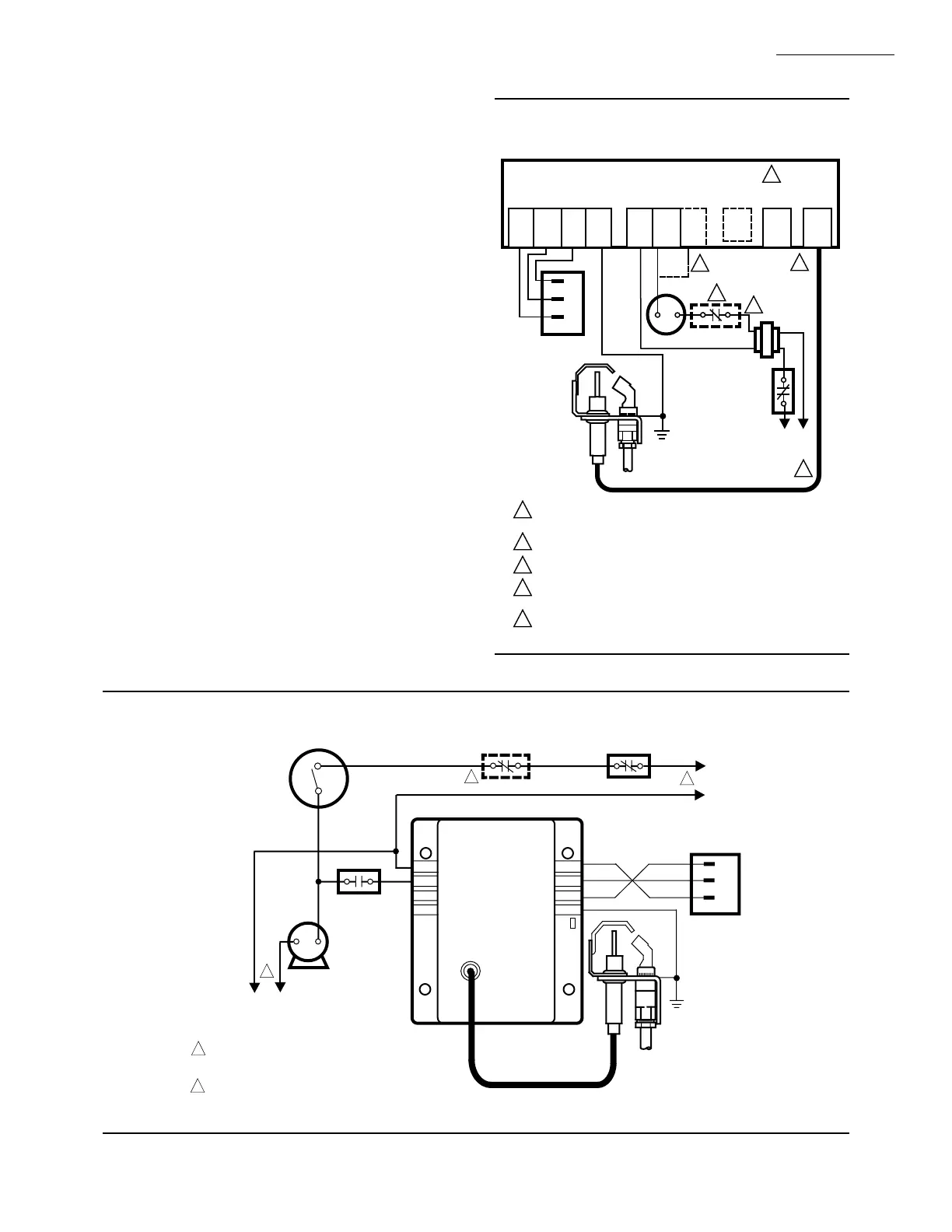
Fig. 9—Wiring connections for 120 volt control in intermittent ignition system.
2
IGNITION MODULE
120V (GND)
MV
GND
(BURNER)
PILOT GAS
SUPPLY
PILOT
BURNER
GROUND
Q345, Q346, Q348, Q362,
Q381 PILOT BURNER/
IGNITER-SENSOR
120V THERMOSTAT
OR CONTROLLER
PV/MV
PV
MV
PV/MV
PV
L1
(HOT)
L2
1
POWER SUPPLY. PROVIDE DISCONNECT MEANS
AND OVERLOAD PROTECTION AS REQUIRED.
ALTERNATE LIMIT CONTROLLER LOCATION.
2
1
LIMIT CONTROLLER
AIR PROVING
SWITCH
COMBUSTION
AIR BLOWER
MOTOR
L2
L1
(HOT)
1
M3082
120V (2)
VR4204
GAS CONTROL
TERMINALS

 Loading...