68-0047—2 6
VR8204; VR4204
INSTALLATION
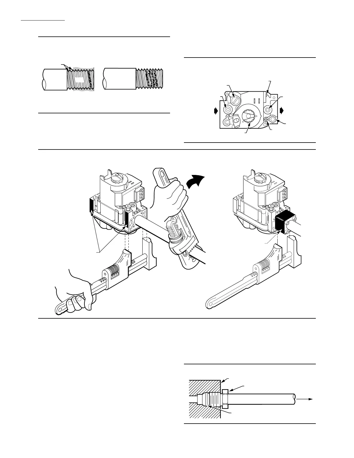
Fig. 4—Use moderate amount of pipe com-
pound.
TWO IMPERFECT
THREADS
GAS CONTROL
THREAD PIPE THE AMOUNT
SHOWN IN TABLE 4 FOR
INSERTION INTO GAS CONTROL
APPLY A MODERATE AMOUNT OF
PIPE COMPOUND TO PIPE ONLY
(LEAVE TWO END THREADS BARE).
M3075A
PIPE
5. Remove seals over control inlet and outlet if neces-
sary.
6. Connect pipe to control inlet and outlet. Use wrench
only on the square ends of the control. If an adapter is used,
place wrench on adapter rather than control. Refer to Figs. 5
and 6.
Fig. 5—Top view of gas control.
OUTLET
PRESSURE TAP
INLET
OUTLET
WIRING
TERMINALS (3)
INLET
PRESSURE TAP
PRESSURE REGULATOR
ADJUSTMENT
(UNDER CAP SCREW)
PILOT OUTLET
PILOT ADJUSTMENT
(UNDER CAP SCREW)
GAS CONTROL KNOB
M3078B
Fig. 6—Proper use of wrench on gas control with and without flanges.
APPLY WRENCH
FROM TOP OR
BOTTOM OF GAS
CONTROL TO
EITHER SHADED AREA
WHEN FLANGE IS NOT USED
APPLY WRENCH
TO FLANGE ONLY
WHEN FLANGE IS USED
M3079
Connect Pilot Gas Tubing
1. Cut tubing to desired length and bend as necessary
for routing to pilot burner. Do not make sharp bends or
deform the tubing. Do not bend tubing at control after
compression nut has been tightened, because this may
result in gas leakage at the connection.
2. Square off and remove burrs from end of tubing.
3. Unscrew brass compression fitting from the pilot
outlet (Fig. 5). Slip the fitting over the tubing and slide out
of the way.
NOTE: When replacing a control, cut off old compression
fitting and replace with the compression fitting provided
on the combination gas control. Never use the old com-
pression fitting because it may not provide a gas-tight
seal.
4. Push tubing into the pilot gas tapping on the outlet
end of the control until it bottoms. While holding tubing all
the way in, slide fitting into place and engage threads; then
turn until finger tight. Tighten one more turn with wrench.
Do not overtighten. Refer to Fig. 7.
Fig. 7—Always use new compression fitting.
GAS CONTROL BODY
TIGHTEN NUT ONE TURN
BEYOND FINGER TIGHT
FITTING BREAKS OFF AND CLINCHES
TUBING AS NUT IS TIGHTENED
TO
BURNER
M3076A

 Loading...