7 60-2080—8
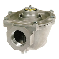
CONNECT PILOT AND BLEED GAS TUBING
(FIG. 4)
1. Square off and remove burrs from end of the tubing.
Bend tubing to the desired form for routing to the pilot
burner. Do not bend tubing at the valve after the compres-
sion nut is tightened because this may result in gas leakage
at the connection.
2. Unscrew brass compression fitting from pilot gas
tapping (Fig. 3). Slip the fitting over the tubing and slide out
of the way.
IMPORTANT: When replacing a valve, cut off old com-
pression fitting and replace with a new compression
fitting. Never use the old compression fitting because
it may not provide a tight gas seal.
3. Push tubing into the pilot gas tapping on the outlet
end of the valve until it bottoms. While holding tubing all
the way in, slide fitting into place and engage threads—turn
until finger tight. Then use wrench and tighten one turn
beyond finger tight.
4. Connect other end of tubing to pilot burner according
to pilot burner manufacturer’s instructions.
5. If required, connect the tubing to bleed gas tapping
(Fig. 3 and 4) as described in step 3. Connect other end of
bleed tubing to main burner or to outside atmosphere.
Fig. 4—Connecting tubing to pilot for bleed
gas tapping.
V48A,F,J; V88A,J
INSTALLATION
b. If a conduit is required, run the conduit through the
opening in the actuator housing, and run the external
wires through the conduit.
c. Using solderless connectors, connect the external
wires to the two 6 in. [152.4 mm] black leadwires
(from the coil).
d. Locate the connections inside the actuator housing.
e. Replace the housing cover, and tighten the cover
screw holding it to the actuator housing.
8. Recheck the wiring circuits before putting the valve
into service.
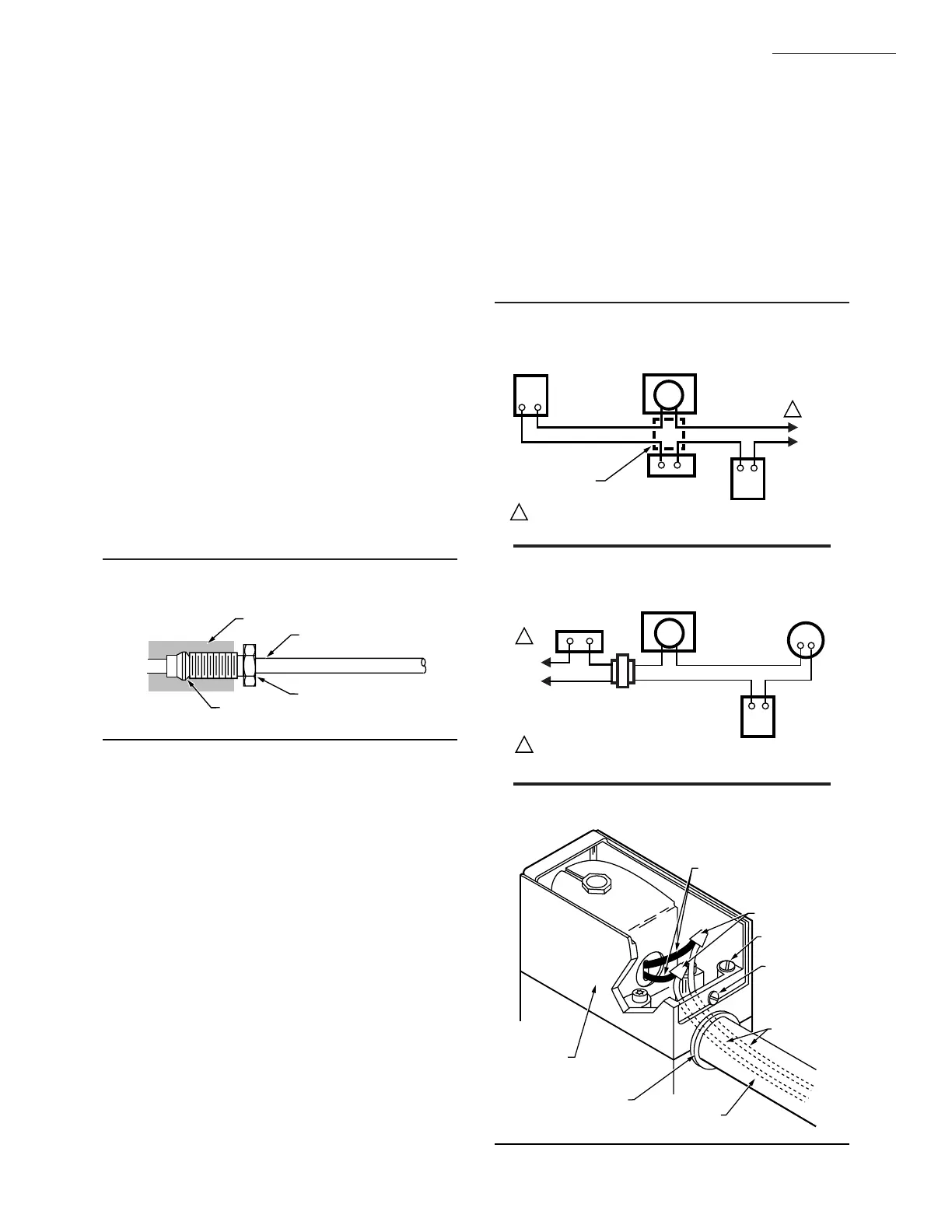
Fig. 5—Typical wiring diagram for V48.
M7302
6 IN. [152.4 MM] INTERNAL
BLACK LEADWIRES
(FROM COIL)
SOLDERLESS
CONNECTORS
GROUNDING
SCREW
EXTERNAL
WIRES
ACTUATOR
HOUSING
OPENING IN
ACTUATOR
HOUSING
CONDUIT
(IF REQUIRED)
COVER
SCREW
M8490
VALVE ACTUATOR
(BLACK LEAD WIRES)
FLAME
SAFEGUARD
CONTROL
L1
(HOT)
L2
1
1
POWER SUPPLY. PROVIDE DISCONNECT MEANS AND OVERLOAD
PROTECTION AS REQUIRED.
LIMIT(S)
LINE VOLTAGE
THERMOSTAT OR
CONTROLLER
JUNCTION
BOX
Fig. 6—Typical wiring diagram for V88.
M8488
LIMIT(S)
VALVE ACTUATOR
(BLACK LEAD WIRES)
24 VOLT
THERMOSTAT
FLAME
SAFEGUARD
CONTROL
TRANSFORMER
L1
(HOT)
L2
1
1
POWER SUPPLY. PROVIDE DISCONNECT MEANS AND OVERLOAD
PROTECTION AS REQUIRED.
Fig. 7—Making wiring connections.
SLEEVE CLINCHES AROUND TUBING
AS NUT IS TIGHTENED
COMPRESSION FITTING
GAS FLOW
TUBING
GAS VALVE
M7300
WIRING
1. Disconnect the power supply before making wiring
connections to prevent electrical shock and equipment
damage.
2. All wiring must comply with applicable electrical
codes, ordinances, and regulations. Use NEC Class 1 (line
voltage) wiring.
3. For normal installations, use moisture-resistant No.
14 wire suitable for at least 167° F [75° C] if using a flame
safeguard primary control, or for at least 194° F [90° C] if
using a flame safeguard programming control.
4. For high temperature installation, use moisture-re-
sistant No. 14 wire selected for a temperature rating above
the maximum operating temperature.
5. Check the power supply circuit. The voltage and
frequency must match those of the valve.
6. Refer to Fig. 5 or 6 for typical field wiring connec-
tions. Follow the burner manufacturer’s wiring diagram if
provided.
7. Make wiring connections inside the actuator housing
(Fig. 7):
a. Loosen the cover screw in the front of the actuator
housing, and remove the housing cover.
 Loading...