EasyManua.ls Logo

Honeywell Velociti AOM-2RF - User Manual

Honeywell Velociti AOM-2RF
2 pages
Print Icon
To Next Page IconTo Next Page
Loading...
AOM-2RF Relay Control Module
INSTALLATION AND MAINTENANCE INSTRUCTIONS
BEFORE INSTALLING
This information is included as a quick reference installation guide. Refer to
the appropriate Gamewell-FCI control panel installation manual for detailed
system information. If the modules will be installed in an existing operational
system, inform the operator and local authority that the system will be tem-
porarily out of service. Disconnect power to the control panel before installing
the modules.
NOTICE: This manual should be left with the owner/user of this equipment.
GENERAL DESCRIPTION
The AOM-2RF Relay Control Module is intended for use in intelligent, two-
wire systems where the individual address of each module is selected using
the built-in rotary switches. It allows a compatible control panel to switch
discrete contacts by code command. The relay contains two isolated sets of
Form-C contacts, which operate as a DPDT switch and are rated in accordance
with the table in the manual. Circuit connections to the relay contacts are
not supervised by the module. The module also has a panel controlled LED
indicator. This module can be used to replace a AOM-2 module that has been
configured for Form-C operation.
COMPATIBILITY REQUIREMENTS
To ensure proper operation, this module shall be connected to a compatible
Gamewell-FCI system control panel (list available from Gamewell-FCI).
SPECIFICATIONS
Normal Operating Voltage: 15 to 32 VDC
Maximum Current Draw: 6.5 mA (LED on)
Average Operating Current: 230µA (LED flashing) Velociti Mode; 255µA (LED flashing) CLIP Mode
EOL Resistance: Not used
Temperature Range: 32˚F to 120˚F (0˚C to 49˚C)
Humidity: 10% to 93% Non-condensing
Dimensions: 4.675" H x 4.275" W x 1.4" D (Mounts to a 4˝ square by 2
1
/8˝ deep box.)
Accessories: SMB500 Electrical Box; CB500 Barrier
I56-3551-006
Velociti
®
Series
FIGURE 1. CONTROLS AND INDICATORS:
C1071-00
RELAY CONTACT RATINGS:
CURRENT RATING MAXIMUM VOLTAGE LOAD DESCRIPTION APPLICATION
2 A 25 VAC PF = 0.35 NON-CODED
3 A 30 VDC RESISTIVE NON-CODED
2 A 30 VDC RESISTIVE CODED
0.46 A 30 VDC (L/R = 20MS) NON-CODED
0.7 A 70.7 VAC PF = 0.35 NON-CODED
0.9 A 125 VDC RESISTIVE NON-CODED
0.5 A 125 VAC PF = 0.75 NON-CODED
0.3 A 125 VAC PF = 0.35 NON-CODED
12 Clintonville Road
Northford, CT 06472-1653
Phone: 203.484.7161;
Fax: 203.484.7118
www.gamewell-fci.com
1 I56-3551-006
02-14
Question and Answer IconNeed help?

Do you have a question about the Honeywell Velociti AOM-2RF and is the answer not in the manual?

Summary

Specifications and Ratings

General Specifications

Details module operating voltage, current draw, temperature range, and dimensions.

Relay Contact Ratings

Lists current, voltage, and load descriptions for relay contacts.

Installation Preparation and Description

Before Installing

Provides pre-installation guidance, including informing authorities and disconnecting power.

General Description

Explains the AOM-2RF module's function in intelligent two-wire systems.

Compatibility Requirements

Specifies the need for a compatible Gamewell-FCI system control panel.

Mounting and Wiring Procedures

Module Mounting

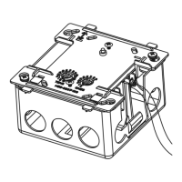
Details how to mount the AOM-2RF module to electrical boxes.

Wiring Instructions

Outlines wiring requirements, including code compliance and barrier usage.

Overview

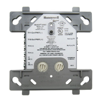
The AOM-2RF Relay Control Module is designed for use in intelligent, two-wire fire alarm systems, allowing a compatible control panel to switch discrete contacts via code command. It is part of the Velociti® Series from Gamewell-FCI, a Honeywell brand. This module is capable of replacing an AOM-2 module that has been configured for Form-C operation.

Function Description:

The primary function of the AOM-2RF is to provide two isolated sets of Form-C contacts, which operate as a Double-Pole, Double-Throw (DPDT) switch. These contacts can be activated by commands from a compatible fire alarm control panel. The module's individual address is set using built-in rotary switches, enabling precise control within the system. It also features a panel-controlled LED indicator for status feedback. The relay switch contacts are shipped in a standby (open) state but may transfer to an activated (closed) state during shipping. It is crucial to ensure the modules communicate with the panel before connecting any circuits controlled by the module to confirm the correct switch state. The module itself does not supervise the circuits connected to its relay contacts.

Important Technical Specifications:

  • Normal Operating Voltage: 15 to 32 VDC.
  • Maximum Current Draw: 6.5 mA (when the LED is on).
  • Average Operating Current:
    • 230µA (LED flashing) in Velociti Mode.
    • 255µA (LED flashing) in CLIP Mode.
  • EOL Resistance: Not used.
  • Temperature Range: 32°F to 120°F (0°C to 49°C).
  • Humidity: 10% to 93% Non-condensing.
  • Dimensions: 4.675" H x 4.275" W x 1.4" D. It mounts to a 4" square by 2⅛" deep electrical box.
  • Accessories: SMB500 Electrical Box; CB500 Barrier.

Relay Contact Ratings (Maximum Voltage and Load Description):

The module supports various load types and current ratings:

  • 2 A: 25 VAC, PF = 0.35 (Non-Coded)
  • 3 A: 30 VDC, Resistive (Non-Coded)
  • 2 A: 30 VDC, Resistive (Coded)
  • 0.46 A: 30 VDC, (L/R = 20MS) (Non-Coded)
  • 0.7 A: 70.7 VAC, PF = 0.35 (Non-Coded)
  • 0.9 A: 125 VDC, Resistive (Non-Coded)
  • 0.5 A: 125 VAC, PF = 0.75 (Non-Coded)
  • 0.3 A: 125 VAC, PF = 0.35 (Non-Coded)

Usage Features:

  • Addressing: The module's address is configured using two rotary switches (TENS and ONES) on the front, allowing for unique identification within the system.
  • Mounting: The AOM-2RF mounts directly to standard 4-inch square electrical boxes with a minimum depth of 2⅛ inches. Gamewell-FCI offers surface-mounted electrical boxes (SMB500) for this purpose. It can also be mounted in a DNR(W) housing.
  • Wiring: All wiring must comply with local codes and regulations. For nonpower-limited applications, the CB500 Module Barrier is required to separate power-limited and nonpower-limited terminals and wiring, ensuring UL compliance. The barrier must be inserted into the junction box, and the module placed within it. The power-limited wiring should be placed in the isolated quadrant of the barrier.
  • Signal Line Circuit (SLC): Connection to the SLC (32 VDC Max) from the control panel or previous device is made via terminals T10 and T11. A twisted pair is recommended for the SLC.
  • Nonpower Limited Wiring: If any wiring to terminals 4-10 is nonpower limited, the CB500 barrier is mandatory. The CB500 includes a nonpower limited label that must be placed over the power-limited terminal information on the nameplate.
  • Compatibility: To ensure proper operation, the module must be connected to a compatible Gamewell-FCI system control panel. A list of compatible panels is available from Gamewell-FCI.

Maintenance Features:

  • Installation Guide: The manual serves as a quick reference installation guide. For detailed system information, users should refer to the appropriate Gamewell-FCI control panel installation manual.
  • Pre-Installation Procedure: Before installing modules in an existing operational system, operators and local authorities must be informed that the system will be temporarily out of service. Power to the control panel must be disconnected before installation.
  • Wiring Best Practices: Wires should be stripped to a length of ¼" to ⅜". Exposed conductors must be secured under the clamping plate and should not protrude beyond the terminal block area. Wires should not be looped under terminals; instead, the wire run should be broken to provide supervision of connections.
  • Documentation: The manual should be left with the owner/user of the equipment for future reference.

Honeywell Velociti AOM-2RF Specifications

General IconGeneral
BrandHoneywell
ModelVelociti AOM-2RF
CategoryControl Unit
LanguageEnglish

Related product manuals