EasyManua.ls Logo

Honeywell WV4262B User Manual

Honeywell WV4262B
12 pages
To Next Page IconTo Next Page
Page #1 background imageLoading...
Page #1 background image
INSTALLATION INSTRUCTIONS
69-2496-03
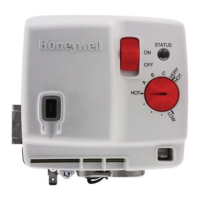
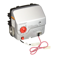
WV4262B Powered Damper
Water Heater Controls
APPLICATION
The WV4262B Water Heater Control System is
designed for power damper water heater applications.
The WV4262B provides these features:
Gas regulation and manual valve features
Intermittent spark-to-pilot ignition
Flame supervision using flame rectification
sensing through the spark rod. This flame sense
circuit uses patented technology to create a
robust sensing signal that is independent of AC
line polarity and appliance earth grounding.
Water temperature sensing using solid state
sensors potted in a submersion well assembly
Manually resettable High Temperature Cutout
(TCO)
Damper motor control with position sensing
Variable resistance flammable vapor sensor with
a sensing and control algorithm to provide
automatic shutdown when hydrocarbon vapors
such as gasoline are detected
Retains up to 10 fault code histories in non-
volatile memory (available through the
EnviraCOM™ communication port)
Solid state setpoint adjustment over a factory
preset temperature range using a linear
potentiometer to provide high resolution
adjustment
Special control features are available to address
items such as stacking. See a Honeywell Product
Specialist for more information.
The specific application of the WV4262B System is
the responsibility of the appliance manufacturer. See
the Specifications below for temperature ranges and
regulator types. The WV4262B system refers to the
combination of the valve and the electronic control
module.
SPECIFICATIONS
IMPORTANT
WV4262B Controls provide direct replace-
ment only; do not substitute other models.
Body Pattern: 90 degree with 1/2 in. inlet and 1/2 in.
inverted flare outlet.
Natural gas model has right-hand threaded
inverted outlet.
LP gas model has left-hand threaded inverted out-
let.
Mounting: Mounting in upright position only.
Electrical Tolerences:
Voltage Minimum: 18 VAC RMS, 60 Hz.
Voltage Maximum: 30 VAC RMS, 60 Hz.
Current in Running Mode: 0.3 Amps @ 24 VAC (plus
inducer motor draw)
Current in Idle Mode: 0.3 Amps Max @ 24 VAC
Damper Relay: 24 VAC RMS, 1 Amp Switching Cur-
rent. 75,000 Cycles Life @ max load.
Capacity: See Table 1.
Conversion: Use conversion factors in Table 2 to
convert capacities for other gases.
Regulation Range (Btuh);
With 1/2 in. NPT inlet and 1/2 in. Inverted Flare Out-
let:
Natural Gas:
Minimum: 30,000
Maximum: 100,000
LP Gas:
Minimum: 40,000.
Maximum: 100,000
Inlet Pressure Range:
See appliance rating plate for Inlet Pressure range
recommendation
1/2 PSI (14.0" w. c.) maximum inlet pressure allowed
for proper operation.
Operational Environment:
Operating Ambient Temperature Range:
32 °F to 150 °F (0 °C to 65 °C)*
Shipping and Storage Temperature Range
-20 °F to 120 °F (-29 °C to 49 °C)
* Gas valve regulation range is guaranteed from 32 °F
to 150 °F (0 °C to 66 °C)

Questions and Answers:

Honeywell WV4262B Specifications

General IconGeneral
BrandHoneywell
ModelWV4262B
CategoryWater Heater
LanguageEnglish

Summary

Application

Specifications

Body Pattern

Specifies the 90-degree pattern with 1/2 in. inlet and 1/2 in. inverted flare outlet.

Mounting

The control must be mounted in an upright position only for proper operation.

Electrical Tolerances

Details voltage, current, and damper relay specifications for the control.

Capacity

Refers to Table 1 for capacity information related to gas flow.

Regulation Range (Btuh)

Specifies the minimum and maximum regulation ranges for Natural Gas and LP Gas.

Inlet Pressure Range

Outlines the recommended inlet pressure range and maximum allowed pressure.

Operational Environment

Defines the acceptable ambient and storage temperature ranges for the control.

Planning the Installation

Frequent Cycling

Control designed for appliances cycling 3-5 times/day; high cycles may reduce lifespan.

Water or Steam Cleaning

Protect control from water/steam during cleaning; mount high to avoid wetting.

High Humidity or Dripping Water

Prevent water drips on control; ensure air circulation in humid environments.

Corrosive Chemicals

Protect control from corrosive chemicals used in cleaning or present in the air.

Dust or Grease Accumulation

Prevent dust/grease buildup which can cause malfunction; use covers if necessary.

Heat

Ensure control's ambient temperature does not exceed rating; use insulation/shielding if needed.

Installation

Location

The WV4262B unit is designed to be mounted on the exterior of the water heater tank.

Install Control to Water Tank

Instructions for screwing the bracket/valve assembly into the spud and connecting the burner fill tube.

Connect Gas Supply

Gas Supply Preparation and Connection

Steps for safely connecting the gas supply, including pipe preparation, trap installation, and sealing.

Wiring

Wiring Connections

Details on connecting the earth ground, electrical harness, and flammable vapor sensor.

Fill Tank

Ensures the water tank is filled before firing the burner to prevent dry tank hazards.

Turn on Main Burner

Procedures for turning on the main burner, including safety checks and setpoint adjustment.

Perform Gas Leak Test

Gas Input and Burner Ignition Check and Adjustment

Perform Flame Current Check

Maintenance

Sequence of Operations

Troubleshooting with LED Indicator Assistance

Troubleshooting without status LED

Instructions to the Homeowner

Turning on the Appliance

Step-by-step guide for turning on the appliance, including safety warnings and troubleshooting.

Turning off the Appliance

Procedure for safely shutting down the appliance, including turning the knob to LOW and turning off gas supply.

Related product manuals