EasyManuals Logo

Honeywell X Series Installation Instruction Sheet

Honeywell X Series
11 pages
To Next Page IconTo Next Page
To Previous Page IconTo Previous Page
Page #9 background imageLoading...
Page #9 background image
43-TV-33-76 iss.2 GLO Jan 21 UK 9
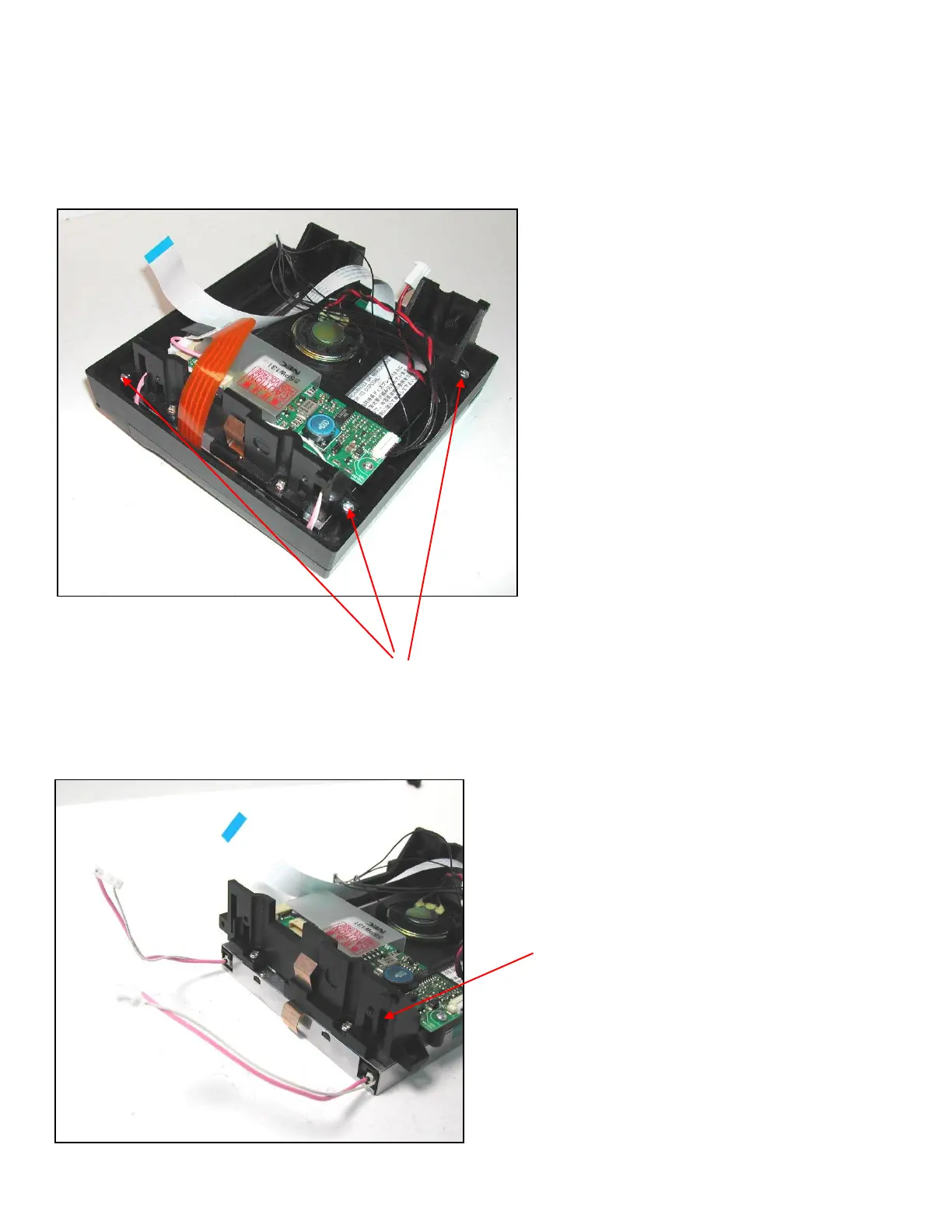
To remove the front bezel and touch screen assembly there are 4 self tapping screws that need to be removed, see Fig
14. Two screws are at the top of the assembly, and two screws are fitted one from each side. When these are removed
the display assembly can be separated.
Take care not to touch the display face or the back of the touch screen, any dirt or finger marks will show when the unit
is re-assembled.
Lift the display assembly out of the front bezel and place it face down. Ensure it is on something that will prevent it
getting scratched or dirty.
Fig 14
4 screws to
release display
assembly
Fig 15
Unplug backlight cables from
inverter and feed through the
holes as shown

Other manuals for Honeywell X Series

Questions and Answers:

Question and Answer IconNeed help?

Do you have a question about the Honeywell X Series and is the answer not in the manual?

Honeywell X Series Specifications

General IconGeneral
BrandHoneywell
ModelX Series
CategoryVoice Recorder
LanguageEnglish

Related product manuals