• a suitable isolating switch providing full disconnection from the mains power
supply is incorporated in the permanent wiring, mounted and positioned to
comply with the local wiring rules and regulations.
The isolating switch must be of an approved type and provide a 3 mm air gap
contact separation in all poles (or in all active [phase] conductors if the local
wiring rules allow for this variation of the requirements)
• the isolating switch will be easily accessible to the customer with the hob
installed
• you consult local building authorities and by-laws if in doubt regarding
installation
• you use heat-resistant and easy-to-clean finishes (such as ceramic tiles) for the
wall surfaces surrounding the hob.
When you have installed the hob, make sure that
• the power supply cable is not accessible through cupboard doors or drawers
• there is adequate flow of fresh air from outside the cabinetry to the base of the
hob
• if the hob is installed above a drawer or cupboard space, a thermal protection
barrier is installed below the base of the hob
• the isolating switch is easily accessible by the customer
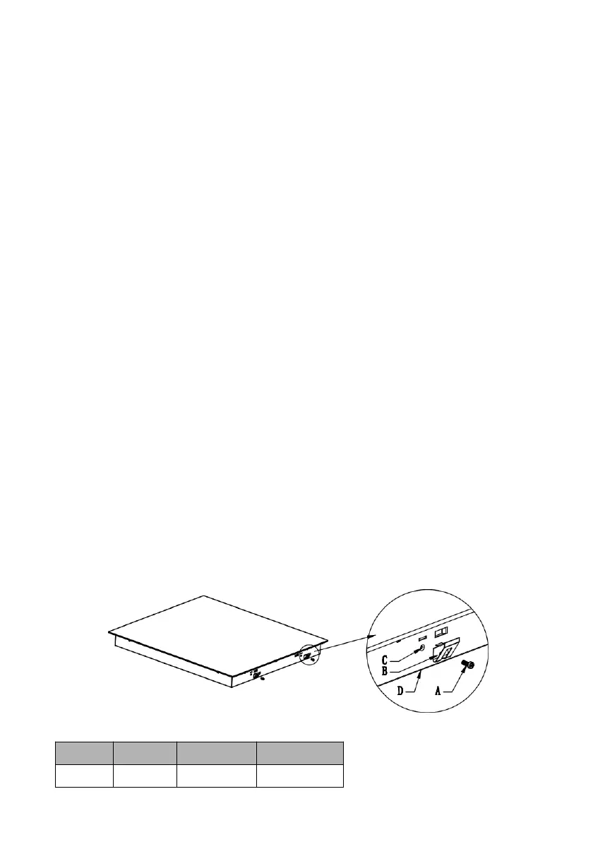
Before locating the fixing brackets
The unit should be placed on a stable,
smooth
surface (use the packaging). Do not
apply force onto the controls protruding from the hob.
Adjusting the bracket position
Fix the hob on the work surface by screw 4 brackets on the bottom case of hob
(see picture) after installation.
 Loading...