
A
Andre DavisAug 4, 2025
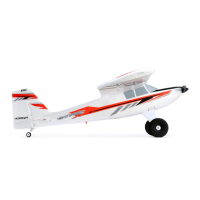
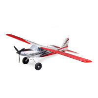
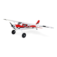
Why is my Horizon Hobby E-FLITE Carbon-Z Cessna 150T 2.1m oscillating?
- CCharles GomezAug 4, 2025
Oscillation in your Horizon Hobby Toy can stem from several issues. It could be due to a damaged or imbalanced propeller or spinner, which requires replacement or balancing. Motor vibration can also cause oscillation, so replace parts, correctly align them, and tighten fasteners. Other potential causes include a loose receiver (align and secure it), loose aircraft controls (tighten or secure parts like servos and control surfaces), worn parts (replace them, especially the propeller, spinner, or servo), or irregular servo movement (replace the servo).