6504.2007 TR10A041-C RE
Note
If the same radio code is programmed for two different
functions, the code for the function first programmed is
deleted and the most recently programmed code remains
valid.
6.1.2 Deleting all the radio codes of a function
1. Select menu P.
2. Select parameter 0, 1 or 2.
3. Press the PRG-button until the decimal points starts
to flash.
4. Press OPEN button () and CLOSE button ()
simultaneously.
5. The decimal point stops flashing; all the codes of
the corresponding function have now been deleted.
6.1.3 Setting the "partial opening" position
(see fig. 22.4)
Note
The "partial opening" position can only be set once the
operator has completed the learning process.
In menu P, the "partial opening" position can be set via
parameter 3. The display flashes slowly. Press the PRG
button and keep it pressed until the decimal point flashes.
Now, the parameter has been activated. Using the OPEN
button () and CLOSE button () the door can be ope-
rated in dead man’s mode.
When the desired position has been reached, press the
PRG button until the display flashes rapidly. The decimal
point goes out and the display flashes slowly.
Note
The setting range of the "partial opening" position ranges
from the OPEN end-of-travel position up to approx.
120 mm (carriage travel) in front of the CLOSE position.
The standard factory setting is approx. 260 mm (carriage
travel) in front of the CLOSE end-of-travel position.
6.1.4 Setting the reversing limit "closing edge safety
device / leading photocell" (see fig. 22.5 )
Note
The reversing limit "closing edge safety device / leading
photocell" can only be set once the operator has completed
the learning process and parameters 3 and 4 in menu 4
have been activated.
In menu P, the setting of the reversing limit "closing
edge safety device / leading photocell" can be set via
parameter 4. The reversing limit "closing edge safety
device / leading photocell" is preset for the closing edge
safety device in front of the CLOSE end-of-travel position.
Parameter 4 is selected and activated, i.e. the PRG but-
ton has to be pressed until the decimal point lights up.
With the OPEN button () the operator is moved to the
OPEN end-of-travel position. Subsequently, a test body
(max. 300 x 50 x 16.25 mm, for instance a folding rule)
is placed on the floor within range of the leading photo-
cell in such a way that the smallest dimension faces
upwards. Press the CLOSE button (). The door travels
downwards until the safety device detects the test body.
The position is stored and checked for plausibility. Then
the operator reverses. If the process has been success-
ful, the display flashes rapidly. The parameter is then
displayed flashing slowly without the decimal point.
Press the PRG button to return to normal operation
(menu 0).
6.2 MENU 2
Select menu 2 by pressing the PRG button. Upon selec-
tion, the menu number remains displayed for a short
period. Afterwards, the active menu parameter (persis-
tence time) is displayed with the decimal point flashing
rapidly.
Press the OPEN button () or the CLOSE button () to
page through the menu. To be able to change the para-
meter, the parameter to be set must be selected. Then
press the PRG button until the decimal point also flashes.
Press the PRG button to return to normal operation
(menu 0).
6.2.1 Setting the operator lighting – persistence time
(see fig. 23.1)
Menu 2 affects the internal light relay. As soon as the
door starts moving, the light relay is switched on, if a
parameter greater than 0 (1-5) has been selected. If
the door has completed its cycle, the operator lighting
remains active for the preset time (persistence time).
ATTENTION
Do not touch the cold-light reflector lamp when
under voltage or shortly after switching off the
lamp
➜ Risk of burning!
6.2.2 Setting the operator lighting – radio signal,
external push-button (see fig. 23.2 )
With parameters 6-9, the time the operator lighting stays
on can be set. The operator lighting can be switched on
via a radio signal or an external push-button (e.g. IT 3b
internal push-button unit).
The operator lighting can also be switched off prematurely
via the same control elements (radio signal or external
push-button).
6.2.3 External radio function of the 2nd channel
(see fig. 23.3 )
If an external 2-channel radio receiver is connected to the
operator, you have the option of using the second channel
for controlling the operator lighting (parameter A).
Note
While the door is moving, the light cannot be switched on
and off!
If the external 2-channel radio receiver is used for partial
opening, parameter b must be activated.
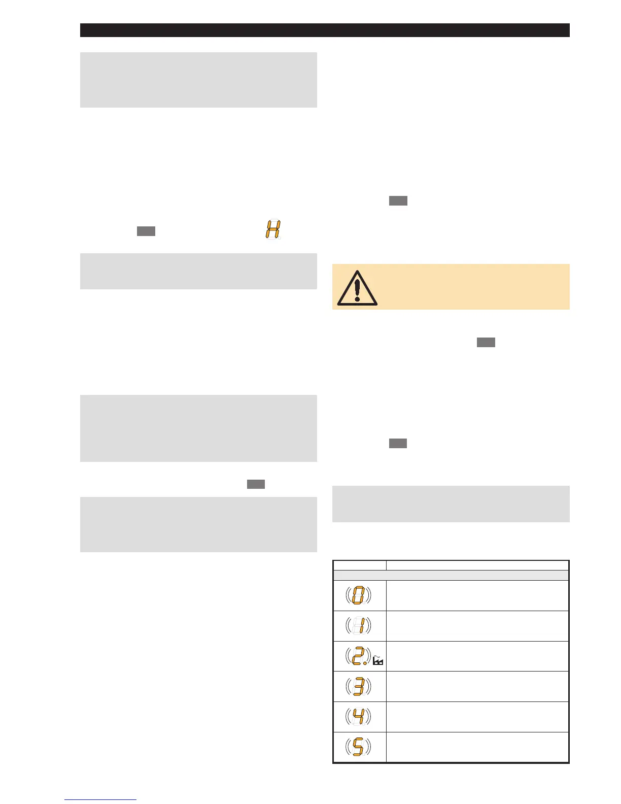
Display Function
Operator lighting persistence time
not active
1 minute
2 minutes
3 minutes
4 minutes
5 minutes
➤
ENGLISH
 Loading...