4
Warning isolate mains supply before commencing
installation.
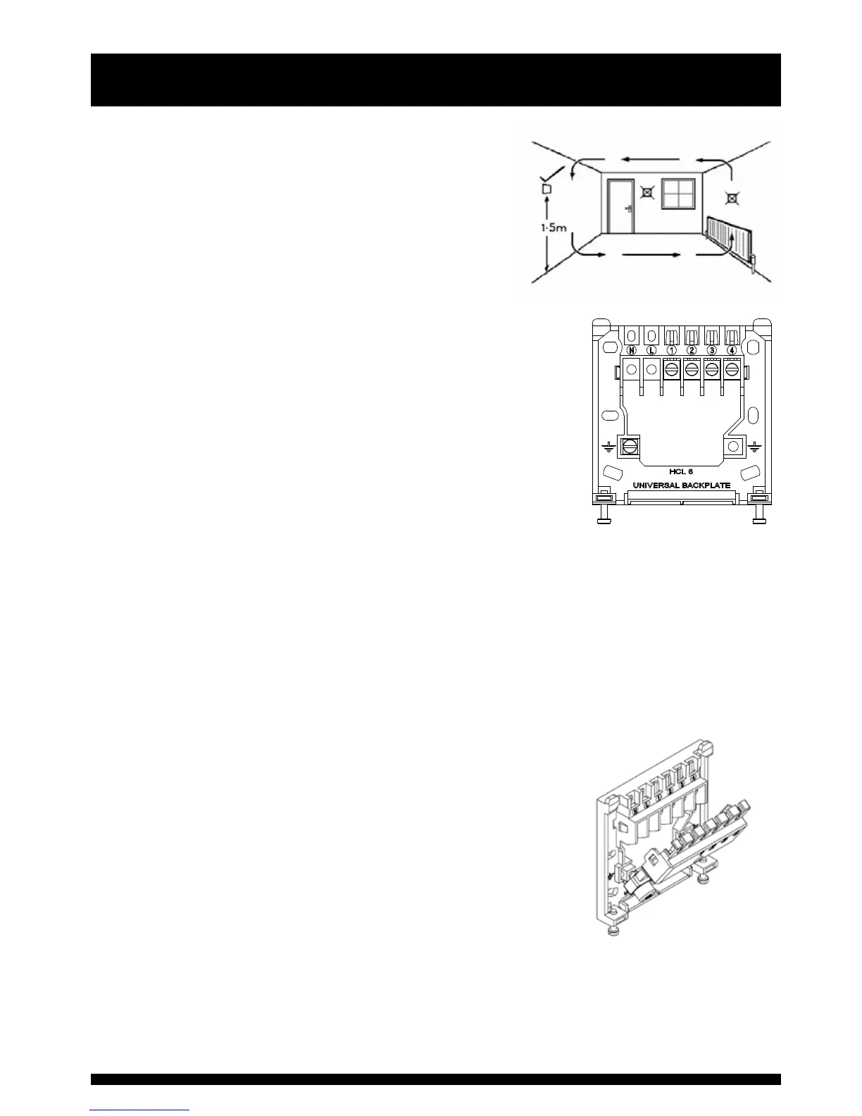
Positioning the Room Thermostat
The HRT4-B should be mounted on an internal wall
approximately 1.5 metres from floor level and should be in a
position away from draughts, direct heat and sunlight. Ensure
that there will be enough space to allow easy access to the
two retaining screws located at the base of the wall plate.
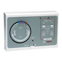
Fitting the wall plate
To remove the wall plate from the HRT4-B undo the two retaining
screws located on the underside, the wall plate should now be easily
removed. Once the wall plate has been removed from the packaging
please ensure the HRT4-B is re-sealed to prevent damage from dust,
debris etc.
The wall plate should be fitted with the wiring terminals located at the
top and in a position which allows a total clearance of at least 50mm
around the HRT4-B thermostat.
Direct Wall Mounting
Offer the plate to the wall in the position the HRT4-B is to be mounted and mark the fixing positions
through the slots in the wall plate. Drill and plug the wall, then secure the plate in position. The
slots in the wall plate will compensate for any misalignment of the fixings.
Wiring Box Mounting
The HRT4-B wall plate may be fitted directly on to a single gang steel flush wiring box complying
with BS4662, using two M3.5 screws. The HRT4-B is suitable for mounting on a flat surface only;
it must not be positioned on an unearthed metal surface.
Electrical Connections
All necessary electrical connections should now be made. Flush
wiring can enter from the rear through the aperture in the wall
plate. For mains voltage applications a 3 Amp fused spur should be
used. The recommended cable size is 1.0mm
2
.
The wall plate is provided with a terminal guard to protect the
user when replacing the batteries. This is supplied with the
wall plate and it is essential that the terminal guard is fitted
after completing the electrical connections to the terminals of
the wall plate.
FAILURE TO DO THIS COULD RESULT IN ELECTRIC SHOCK WHEN CHANGING BATTERIES.
As access to the terminals will not be possible once the terminal guard is fitted only fit the guard
when all wiring is complete and the system checked for correct operation.
Installation Instructions