WEGA 2.2 4025122-001
Instructions for Use
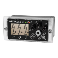
Displays (LCD symbols):
Arrow: This indication means ‚voltage present‘ according to IEC 61243-5 (VDE 0682, Part 415).
It appears in the range of 0.10…0.45 * U
n
.
Dot:Thisindicationmeansthatthecurrentowingthroughtheindicationdeviceatavalueof
Un/√3correspondstoitsrespectivesetpoint.Duetothispermanentmonitoringofcurrentitisnot
necessary to perform a repetition test.
Flashing wrench:
The occurrence of the following errors lead to darkening of the arrow and dot symbols and the tool
symbol appears on the respective phase indication:
• Earthfault
• Interruptionoftheconnectioncable
• Short-circuitoftheconnectionline
If the overall system is in voltage-free condition (U < 0.10 * U
n
), all of the three wrenches (active
zero-voltageindication)startashing.
4.2 Mechanical characteristics
Dimensions: 96mm x 48mm x 42.5mm,
Plug-in housing for panel mount A 96 x 48 according to DIN 43700,
Panel cut-out: 92+0.8mm x 45+0.6mm
Degree of protection: IP 54
Housing material: Polycarbonate
Total weight: approx. 280g
Measuring / earth socket: LRM system. Distance between sockets 14mm, dia. 4mm
4.3 Remote indication
The remote indication signals are fed out via a 6-pole plug-in connection on the rear side of the
WEGA 2.2 device (see picture 2).
Data of the relays: Type DSP1-DC12V
Permanent contacts
Contact rating: 5A / 250V AC (1250VA)
(Max. switching capacity) 5A / 30V DC (150W)
Insulating voltage: 1000V
RMS
between open contacts
3000V
RMS
between contacts and coil
Shock resistance: 20 G
Vibration resistance: 12 G
5
Dipl.-Ing. H. Horstmann GmbH