WEGA 2.2 4025122-001
Instructions for Use
5.4 Voltage testing
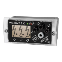
The integrated WEGA 2.2 voltage detecting system is designed for continuous operation. Due to this
feature the WEGA 2.2 provides continuous voltage testing in the switchgear unit into which it has
been installed displaying the „Voltage Present“ condition by illuminated arrow and dot symbols.
According to VDE 105 Part 1 and Part 100 for xed-mounted devices, the user must verify the
voltage-free condition of the disconnected switchgear components by viewing the changes in the
display while the voltage is switched off.
Description of the visual indications in case of voltage testing: Refer to item 4. Technical data
Attention! If no voltage is detected on all three phases, check the integrated WEGA 2.2 voltage
testing system for proper function. If any of the dened indications fails to appear during
function testing, this will be a sign that the integrated voltage detecting system is defect. In
this case its indication must not be made use of for the evaluation of voltage conditions.
5.5 Phase comparison
The phase comparison is performed by means of a phase comparator for LRM systems according to
IEC61481(VDE0682Part415),e.g.theOrion3.0madebyHorstmannGmbH,whichisxedonto
the LRM interface on the front plate. The sockets are accessible after the protection caps have been
removed.
The attachment of the phase comparator to the device may result in a weaker illumination of the
corresponding arrow and dot symbols of the WEGA 2.2.
Rextheprotectioncapafterthephasecomparisonhasbeennished.
5.6 Relay signals
Therelay„VoltagePresent“or„U≠0“isswitchedonwhenthevoltageofatleastone •
phase is greater than 0.45 * U
n
.
The relay „No Voltage Present“ or „U = 0“ is switched on when the voltage of at least one •
phase is less than 0.10 * U
n
.
Each of the two relays has a change-over contact with a common connection
(C - Common), a normally closed contact (NC - normally closed) and a normally open contact
(NO - normally open). The relays contacts are electrically isolated from the measuring voltage and
auxiliary voltage. Depending on the value of the measuring signal the following relay functions will
be tripped:
Voltage applied to phase:
Auxiliary
voltage
Relay
“Voltage
Present”
U≠0
Relay
“No Voltage
Present”
U = 0
L1 L2 L3
U > 0,45 * U
n
U > 0,45 * U
n
U > 0,45 * U
n
ON On OFF
U > 0,45 * U
n
U > 0,45 * U
n
U < 0,10 * U
n
ON ON ON
U > 0,45 * U
n
U < 0,10 * U
n
U < 0,10 * U
n
ON ON ON
U < 0,10 * U
n
U < 0,10 * U
n
U < 0,10 * U
n
ON OFF ON
ANY ANY ANY OFF OFF OFF
Remarks to the table:
For the sake of clarity the table does not show all possible combinations of measuring and auxiliary
voltages.
7
Dipl.-Ing. H. Horstmann GmbH

 Loading...