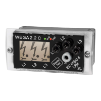
WEGA 2.2 4025122-001
Instructions for Use
The relays in de-energized position („Relays OFF“) is shown on the rear side of the voltage
detecting system.
5.7 Monitoring of auxiliary voltage
Thefailureofauxiliaryvoltageisidentiablebythefollowingoccurrences:
• IlluminationoftheLCDdisplayisnotswitchedon.
• Bothrelays(U=0undU≠0)areswitchedoffatthesametime.
• NoneofthesymbolswillappearontheLCDdisplay(noarrow,dotsymbolorashing
wrenches).
Check the auxiliary voltage in all three cases.
6. Storage, maintenance and transportation
Ensure that the integrated WEGA 2.2 voltage detecting systems are stored and transported in a
dry and clean environment. Avoid any damages to it. Do not use any damaged devices with lack of
proper functioning and safety or with illegible inscriptions. It is mandatory that the user checks the
device for proper condition prior to each installation.
Attention! Any warranty claim is void in the case of damages caused by non-observance of
these operating instructions. We are not liable for consequential damages arising out of or
relating to this non-observance.
7. Maintenance
Ensure that the integrated WEGA 2.2 voltage detecting systems are kept in a clean and dry
environment, apart from that they do not require any maintenance. After having carried out a phase
comparison or a function test the user must take care that the protection cap is reattached to the
sockets of the LRM interface.
8. Maintenance test
Theappearanceofthedotsymbolgivesproofthatthecurrentowingthroughtheindicationdevice
complies with the requirements according to IEC 61243-5 (VDE 0682 Part 415) for voltage detecting
systems (VDS).
Due to this permanent monitoring feature, a maintenance test according to this standard is not
necessary.
Order No:
WEGA 2.2 51-2200-001
Accessory:
Orion 3.0: 51-0206-006
Measuring module NO-M
(for the measurement of the current
of the measuring socket): 51-0207-010
8
Dipl.-Ing. H. Horstmann GmbH

 Loading...