Do you have a question about the Hoshizaki KMS-1402MLJ and is the answer not in the manual?
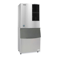
Details the specific icemaker model and its type for service.
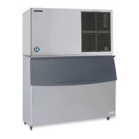
Identifies the compatible condensing unit models covered in this manual.
Provides essential safety guidelines to prevent injury and appliance damage.
Lists phone numbers and email for obtaining technical assistance.
Explains warning symbols and proper use of the icemaker.
Outlines critical safety measures to reduce risks during operation.
Details safety concerns specific to KMS and SRK appliance models.
Provides guidance on proper placement to avoid water damage.
Illustrates and labels the various parts of the icemaker unit.
Shows and labels the components of the SRK condensing unit.
Presents a unified diagram of the water and refrigeration circuits.
Details the sequence of operation for the icemaking cycles.
Lists components energized when the unit is in service mode.
Illustrates the different states and transitions during shutdown and restart.
Explains parameters for freeze time correction and its operational flowchart.
Covers essential warnings and preliminary steps for diagnosing issues.
Lists requirements for correct installation to ensure proper function.
Details steps for diagnosing issues after powering on and checking fuses.
Provides diagnostic steps for HPS and Discharge Line Thermostat.
Covers diagnosis of components during the initial fill and harvest cycles.
Guides on diagnosing issues with the compressor and HGVs.
Outlines the procedure for diagnosing LLV issues.
Details diagnostic steps for specific relays X10, X12, and X13.
Covers diagnosis for X11 relay and associated drain valve checks.
Provides steps for diagnosing the harvest pump timer function.
Explains how to diagnose issues with harvest cycle termination.
Details diagnosis of components during the freeze cycle.
Covers issues related to compressor, FMRs, and valves during freeze.
Diagnoses issues with pump motor, LLVs, refrigerant, and TXV.
Addresses problems with freeze cycle termination and short cycles.
Details diagnosis of the pump-out cycle and control board status.
Guides on diagnosing pump motor and drain valve operations.
Covers diagnosis for DV, X10, X11, and X13 relays.
Addresses shutdown diagnosis and freeze-time correction checks.
Explains the initiation of freeze time correction based on differential.
Describes the sequence of freeze-time correction occurrences and steps.
Details how to reset the appliance cycle and control board alarms.
Covers alarm reset and preliminary checks of the control board.
Explains how to perform an output test and check LED sequences.
Details voltage checks for control board connectors K3, K4, and K5.
Describes how to test the continuity of the bin control proximity switch.
Provides step-by-step instructions for cleaning the bin control.
Details testing float switch continuity and operational function.
Outlines the process for cleaning the float switch assembly.
Details how to measure thermistor resistance for testing.
Explains the functions of the control switch in its different positions.
Describes the three functions of the service switch.
Lists potential causes and checks for the 'No Ice Production' issue.
Covers diagnostic steps for compressor, valve, and motor problems.
Identifies potential causes for freeze-up in both harvest and freeze cycles.
Lists potential causes for reduced ice production during cycles.
Details checklist items related to appliance operation and initial setup.
Lists checklist items for appliance status and corrective actions.
Provides guidance on safely handling the control board to prevent static damage.
Illustrates the control board and identifies its components and connectors.
Explains the meaning of sequence step LEDs and energized components.
Details audible alarms and specific LED blinking patterns.
Shows the factory default settings for S4 and S5 dip switches.
Explains how to adjust harvest time using S4 dip switches 1 and 2.
Details pump-out time settings using S4 dip switches 3 and 4.
Describes the pump-out frequency control using S4 dip switch 5.
Explains harvest pump time settings using S4 dip switch 6.
Covers settings for harvest assist and freeze-time correction.
Explains the purpose and setting of S4 dip switch 8 for factory use.
Details freeze timer settings using S4 dip switches 9 and 10.
Explains the float switch control selector using S5 dip switch 1.
Describes refill counter settings using S5 dip switches 2 and 3.
Details minimum harvest time settings using S5 dip switch 4.
Explains the anti-slush control function using S5 dip switch 5.
Covers essential warnings and notices for refrigeration circuit repairs.
Details the proper procedures for recovering and handling refrigerant.
Provides guidance on brazing and replacing the refrigerant drier.
Outlines the steps for evacuating and recharging the R-404A system.
Details the specific method for liquid charging R-404A systems.
Provides replacement notes for key refrigeration components.
Offers guidance on installing fan motors and thermistors.
Lists regular maintenance tasks for daily, bi-weekly, and monthly intervals.
Details annual tasks including cleaning and inspection of the icemaker.
Outlines steps for preparing the appliance for storage or cold conditions.
Provides detailed steps for draining water lines and cleaning the bin.
Covers requirements for refrigerant recovery and compliant disposal.
Presents electrical specs and consumption data for KMS-1402MLJ with SRK-15J.
Provides performance data on ice production and cycle times.
Presents electrical specs and consumption data for KMS-1402MLJ with SRK-15J3.
Provides performance data on ice production and cycle times for the SRK-15J3.
Details electrical, dimensional, and refrigeration circuit specifications for SRK-15J.
Details electrical, dimensional, and refrigeration circuit specifications for SRK-15J3.
Illustrates the wiring harness connections linking the KMS and SRK units.
Shows specific wiring details for SRK (1 Phase) components.
Shows specific wiring details for SRK (3 Phase) components.
| Type | Modular Ice Maker |
|---|---|
| Refrigerant | R-404A |
| Voltage | 208-230V |
| Ice Production Capacity | 1, 400 lbs/24 hrs |
| Power Supply | 208-230V/60Hz/1-Phase |