Do you have a question about the Hotpoint ULTIMA FDW80 and is the answer not in the manual?
| Delayed start timer | Yes |
|---|---|
| AquaStop function | Yes |
| Adjustable feet | Yes |
| Salt indicator | Yes |
| Rinse aid indicator | Yes |
| Water consumption per cycle | 9.5 L |
| Power consumption (off) | 0.5 W |
| AC input voltage | 220 - 240 V |
| AC input frequency | 50 Hz |
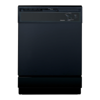
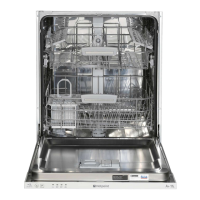
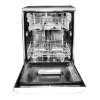
| Product size | Full-size |
| Washing programs | Eco, Intensive, Normal, Pre-wash, Rapid |
| Delay start (max) | 24 hours |
Provides essential safety precautions and general advice for servicing the appliance.
Describes various wash cycles, their selection instructions, descriptions, detergent, rinse aid, and duration.
Covers positioning, levelling, water and electrical connections, earthing, and anti-flood protection.
Emphasizes unplugging the machine and being aware of sharp edges before dismantling.
Provides step-by-step instructions for removing the top cover, panels, console, and modules.
Details the process for removing door latch, LCD module, drain pump, circulation motor, and heater.
Covers the removal of the turbidity sensor, fill valve, mains neon, pressure switch, and turbo dry fan/condenser.
Provides instructions and figures for removing and refitting the sump assembly using a special tool.
Lists error codes (AL 01-99, H20) and their potential causes for troubleshooting.
Provides detailed explanations and troubleshooting steps for specific fault codes like A01, A02, A03, A04, A05.
Continues detailing fault codes A06, A08, A09, A10, and explains filling faults and wash pump issues.
Presents the electrical wiring diagram for FDW80 and FDW85 models with Bit100 controls.