16
Operations
The purpose of venting a gas pressure washer is to
completely remove all products of combustion and to
vent gases to the outside air without condensation in
the vent or spillage at the draft hood (except in cases of
downdraft or poor stack conditions). To assure correct
venting, use a strong, gas-tight insulated pipe with a
cross section equal to that of the flue collar or draft
hood outlet and of sufficient vertical height.
During vent installation, avoid sharp turns, long hori-
zontal runs and improper pitches. Maintain proper
support of vent connectors and joints, observe clear-
ances from all combustibles and top the vent outlet with
an approved cap.
Type "B", due to its temperature rating, can only be
used with natural draft pressure washers. A "B" vent is
designed for exhaust temperatures not to exceed
470°F (245°C).
All venting installations must conform to local codes. In
the absence of local codes, refer to "National Fuel Gas
Code" NFPA 54 and be constructed of materials
approved by the Uniform Building Code.
Vents penetrating ceilings or walls should be double-
wall approved appliance vents and should be one to
two inches from combustibles. Vents passing through
enclosed spaces and vents exposed to the weather
should also be the double-wall type. Sometimes vents
have to be built of such great length that they come
apart at their joints under their own weight. These
should be screwed together at the joints with sheet
metal screws, usually three per joint. If the inspector
indicates that the vent is too close to combustibles, it
may be necessary to chisel away some of the combus-
tible or route the vent pipe around the combustible. The
cross-sectional area of any flue shall not be less that
the cross-sectional area of the flue vent connection
outlet of machine.
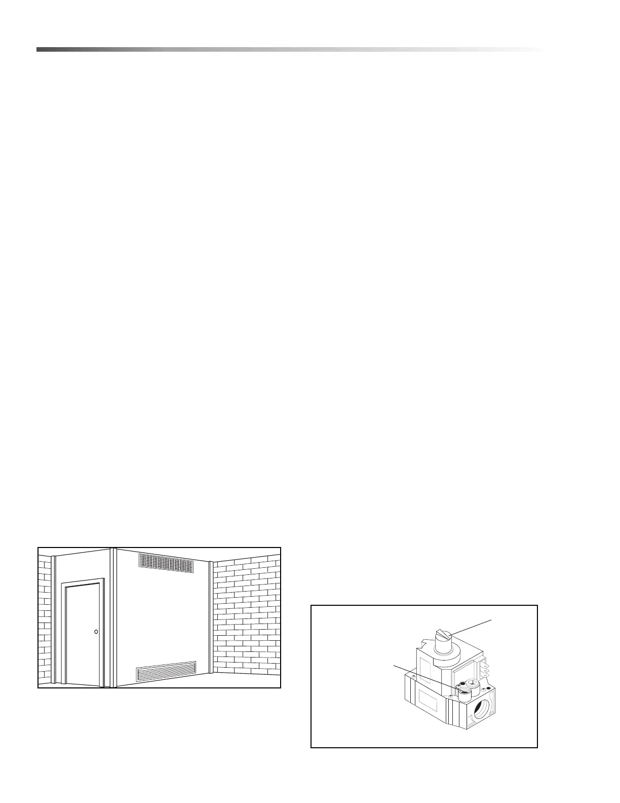
Ventilation
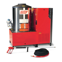
Water Source:
The water source for the machine should be supplied
by a 5/8" I.D. garden hose with a city water pressure of
not less than 30 PSI. If the water supply is inadequate,
or if the garden hose is kinked, the machine will run
very rough and the burner will not fire.
Water Connection:
Connect the high pressure hose by pulling the coupler
collar back and then inserting it onto the discharge
nipple. Secure it by pushing the collar forward.
Attach the wand into the spray gun using teflon tape on
the pipe threads to avoid leaks.
Inspection and Testing Gas Piping:
The building structure should not be weakened by
installing the gas piping. The piping should not be
supported by other piping, but should be firmly
supported with gas hooks, straps, bands or hangers.
Butt or lap welded pipe should not be run through or in
an air duct or clothes chute.
Before turning gas under pressure into piping, all
openings from which gas can escape should be closed.
Immediately after turning on gas, the system should be
checked for leaks. This can be done by watching the
1/2 cubic foot test dial for 5 minutes for any movement
or by soaping each pipe connection and watching for
bubbles. If a leak is found, make the necessary repairs
and repeat the above test.
Defective pipes or fittings should be replaced and not
repaired. Never use a flame or fire in any form to locate
gas leaks — use a soap solution.
After the piping and meter have been checked
completely, purge the system of air. DO NOT bleed the
air inside an enclosed room.
During pressure testing of the system at test pressures
in excess of 1/2 PSIG, the pressure washer and its indi-
vidual shut-off valve must be disconnected from gas
supply piping system or damage to the gas valve will
occur.
Hotsy 900/1400 Operator’s Manual 9.803-325.0 - C
Illustration showing air openings necessary
to supply air for combustion when installed
in an enclosed room.
On/Off
Switch
Manifold
Pressure Adjustment
Screw Under Cap
 Loading...