EL-MF877-00 Page 2
Template Revision B
Tool Description Tool Size (if
applicable)
Screw driver 2#
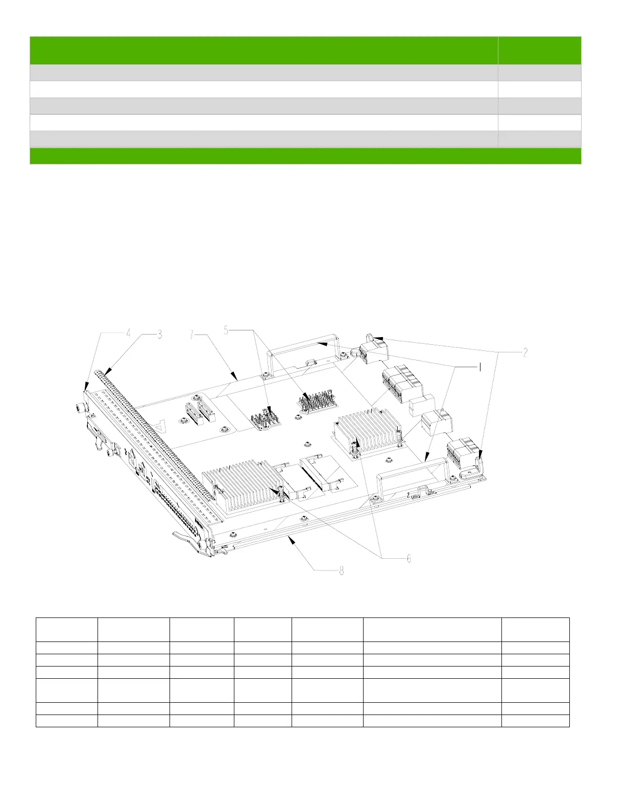
3.0 Product Disassembly Process
3.1 List the basic steps that should typically be followed to remove components and materials requiring selective treatment:
1. Unscrew the screws on part 1,then remove part 1;
2. Unscrew the screws on guiding set 2,then remove guiding set 2;
3. Remove shielding finger 3 from panel 8;
4. Remove film 4 from panel 8;
5. Unscrew the screws on heatsink 6,then remove heatsink 6 from pcb 7;
6. Remove heatsink 5 from pcb 7;
7. Unscrew the screws on PCB 7,then remove PCB 7 from bottom panel 8.
3.2 Optional Graphic. If the disassembly process is complex, insert a graphic illustration below to identify the items
contained in the product that require selective treatment (with descriptions and arrows identifying locations).
Figure1 Treatments to the product
3.3 Material of the facility built
Facility Components Material Weight(g) Weight
percentage
Selective treatment for
materials and components
Details
1 Fe 48 1.67% Fe recycling
2 Zn 32 1.11% Zn recycling
3 Be-Cu 2.7 0.09% Cu recycling
4 PC 9.2 0.32% Pla
recycling
5 Al 10.5 0.37% Al recycling
6 Al 225 7.84% Al recycling

 Loading...