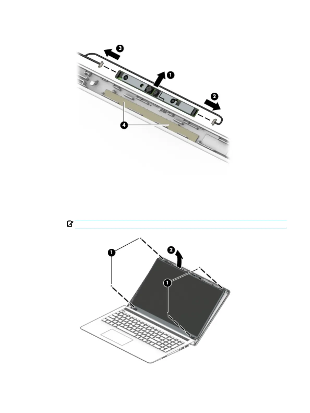
d. Remove the tape from the enclosure (4). Replacement cameras come with tape already installed.
4. To remove the display panel:
a. Remove the four Phillips PM2.0×3.0 screws (1) that secure the display panel to the enclosure.
b. Rotate the display panel onto the keyboard (2) to gain access to the display cable connection on
the back of the panel.
NOTE: The display will not be connected to the computer as shown in the following image.
Component replacement procedures 61
 Loading...