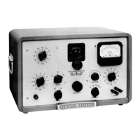
An
additional set of binding posts, identical in type and arrange-
ment with those on the control panel, is provided at the rear of
the instrument. This set of four terminals is connected inparallel
with the binding posts on the control panel.
CT
-
This binding post is the impedance-matching
transformer center -tap terminal.
OUTPUT
-
These two binding posts are the output terminals
for the Model 206A Signal Generator.
G
-
This binding post is connected to the chassis.
By patching to terminal
G
any of the binding
posts may be connected to the chassis.
RANGE
This rotary switch controls the magnitude of the resistance in the
frequency-determining circuits. The position of the RANGE switch
indicates the multiplying factor for the tuning dial indication.
FREQUENCY
This knob is the fine control for adjusting the capacity in the fre-
quency-determining circuits of the Model
206A.
The coarse control for the frequency-determining capacity
adjustment is directly connected to the tuning dial and capaci-
tor drive mechanism. The coarse control is the knob imme-
diately below the tuning dial.
The tuning dial is calibrated in cycles per second for the
lowest range, and its indication multiplied by the factor
indicated by the RANGE switch will give the actual output
frequency of the oscillator.
AMPLITUDE
This knob varies the setting of the variable resistor which controls
the level of the input to the output amplifier. The voltage level of
the amplifier output is indicated by the meter on the control panel.

 Loading...